
MikeGTW
Signalman, ESQ
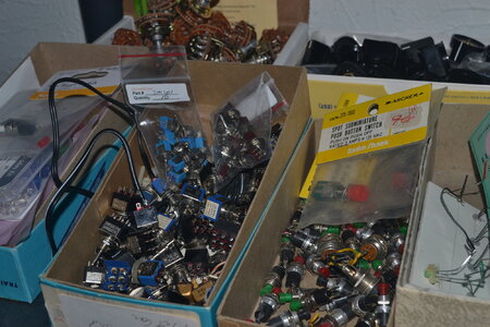
They will work just take up more room then a toggle sw How many are you going to need ?I have decided to use single pole light switches for power to tracks on/off. Can buy a cheap 15 amp switch for $1.40, can’t find a toggle switch for much less than $3, good or bad option? I want each block with its own power to trace a short easier, make sense?
Just found light switches for under a buck, be a sizable savings if you guys think they will work…
One other thing no on off light so you can tell which ones on or off
I had a bunch of the older type toggles somewhere Just the basement is such a mess right now I know I have some smaller ones in the workshop room
Also are you still thinking about the caboose ind for your switches how many
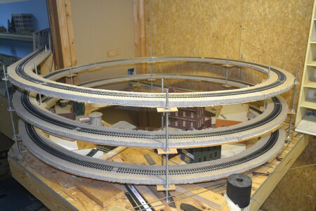
 Second cut I did wide enough to bring a stream down (if I can pull it off…)

