Interesting track plan, Tupper Lake & Faust Junction


Corner Real Estate

Quite a number of industries/structures have been considered for this corner piece of real estate.
area and initial thoughts.jpg


Most recently I had moved 'Allied Rail Rebuilders' out of that very corner, and out to an open field in front of the bridge portion of the stone arch viaduct.


My intention was to pursue placing a power plant scene in that corner location, building flat of that power plant against the backdrop , image of big coal pile on the backdrop, then electrical distribution structure out in front of the plant. (and maybe 3 smoke stacks).


Oops, .....this morning I unpacked and was taking photos of the coke structures that were part of that steel mill scene I bought a few years ago. I figured I might as well sell this structure off as there is no way I would have room for it down near my steel mill. I had never really looked at one of these coke plants that closely, nor considered utilizing one on my layout.


BUT I got to thinking, that being another coal consumer, would this structure fit into that corner along with the coal fired power plant?....just maybe? It is a pretty interesting structure that could stand on its own rather than being directly attached to the steel mill.


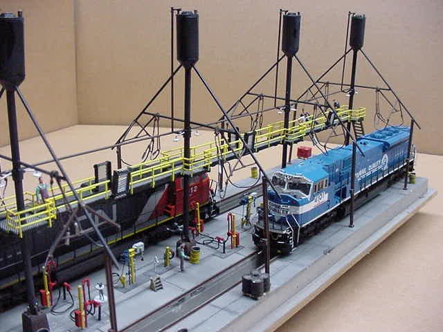
So here is a little mock-up I did,..


DSCF5021.JPG


DSCF5022.JPG


DSCF5024.JPG


DSCF5023.JPG


I'm liking it,...even while I will be accused of 'too much' in a small space
 
Awhile back I got this suggestion given to me about a few of my errors.

Hi Brian,


Have a look at the next 2 photos


Photo1 showing a new coal delivery track. Keep an eye on the area labelled "Bench".


Key points


  • rotate the whole Quench structure 180 degrees so that the Quench tower over the Benzol Track is over the Hot Car track. The quench tower's sole reason for existence is to quench hot coke moved from the ovens by the hotcar before the coke burns away to nothing.
  • a new Coal-In track - given the number of ovens and that it takes 16-24 hours to cook an oven of coal for pushing as coke and at about 20 tons/oven, then its feasible we can have a short Coal-In Track that takes about 2 by 100-ton cars of coal at a time several times daily that would meet the oven's requirements and not take up much space.
  • a Coke-Out track
  • The Benzol track can be fitted with a high-level tank-loading platform for loading out by-products such as Benzol, Napthalene, Toluene, etc.A photo of a By-products plant can be pasted on the backscene.

The next photo show the location of some of the new structure that would tie it all together.


New structures


  • Gate - to isolate the hotcar track from the rest of the layout. Hotcars are usually captive to the battery. We can go into the finer points their design later.
  • Wharf - Ideally this should be long enough to "catch" multiple loads of coke dumped by the hot car. However we could get away with a short wharf of about 2-3 hotcar lengths.
  • Dump - on the Coal-In track simply a corrugated iron roof and sidewall to cover a non-visible hopper and conveyor belt that feeds across to the other conveyor that heads up to the coal bin above the battery
  • Tanks - small concrete pondages that allow any coke fines in the runoff quench water to settle out before the surplus quench water is returned to tanks in the top of the building next to the quencher. About 4/5 of the quench water doesn't escape as steam and is recycled to the quencher tanks.
  • Quench stack - not shown - This is a large diameter stack that allows steam to escape from the quencher (for HO think about the size of the cardboard cylinder in a roll of hand towel) This is adjcaent to the concrete quencher structure, where-ever you can fit it in.
  • Screens - ideally there should be 2-tracks out, one for "small" and the other for "lump". The lump feed goes to the blast furnace highline and the smalls go to domestic markets (foundries/household use etc) or are used as feed at a sinter plant. One of the coaling tower kits could be re-purposed as the screens. Your unused conveyor runs from the wharf to the screens.

That ought to do to get your thinking started,
Regards,
John Garaty

I was glad to get this knowledgeable info from a fellow who actually worked at a coke plant.
 
Then I got this info,...
if its got the coke collecting car (hotcar) and its tracks with the quencher chamber, then that is the "coke side" . If your model has the ram on it, then that's the "pusher side".


The big pipe with the yellow arrow is the gas off-take main This took the gas and other compounds liberated during the coking process off to the by-products plant for separation into gas, sulphate of ammonia, benzol, toluene, tar and other compounds. On all the batteries at Port Kembla, this gas main was on the coke side, but I can think of no real engineering reason why this should be so.


As far as light coming from the battery, on the coke side the only light would come from the oven that was in the process of being pushed. The door extractor machine that runs along the coke bench beside the hotcar track on the has 2 purposes. The first is to take out the coke side oven door prior to pushing and then to re-install the cokeside oven door after the oven is pushed. The second purpose is to insert the coke guide into the oven after the cokeside door is removed. The coke guide forms a hollow channel the height and width of the oven that carries the coke across into the hotcar while the oven is being pushed. The will be a continuous red/yellow glow from the oven that can be seen while the coke guide is in place or when the extractor moves clear of the oven after the push so any spillage can be cleared from the bench before the extractor moves back in to re-install the oven door.


The oven also has to be "taken off main" before the doors can be removed from either side for pushing. This involves "lifting the lid" and doing some other stuff on the vertical standpipe that feeds across to the gas off-take main (with the yellow arrow). While the oven is "off main", there is usually flame coming from the top of the standpipe. The oven "goes back on main" after both oven doors have been re-installed after the oven has been pushed and the oven has been charged and levelled.


Usually there is very little light from the pusher side, even when the door is out for the push because the ram and its equipment gets in the way. As soon as the pusher side door is removed, the ram beam is inserted just into the oven, The front of the ram beam is used to support the face of the coke in the oven before it is actually pushed, but this also prevents a lot of light form escaping from the oven..After the push, the ram beam comes back into the ram and the tall vertical face of the front of the ram beam would probably be only about 5' to 10' back from the oven edge. Any coke spillage is quickly shovelled back into the oven before the pusher side oven door is replaced.


Hotcars are usually restricted to each oven battery but they can be shared between batteries while the adjacent battery's hotcar is down for maintenance. This is not ideal because it slows down the pushing rate of both oven batteries. At Port Kembla we had 6 separate oven batteries all lined up on the one hotcar track. In the mid 1970's #2 Battery was dead, but the hotcar from #3 Battery ran through to either #1 or #4 battery. Another part of the trainee's duty was to be the "observer" when this happened.


Hotcars are very specialised pieces of equipment. The driving locomotive is electrically powered by live rails under the side of the coke bench. The actual catching wagon has an angled deck on it and is robust enough to take having several thousand gallons of water dropped on every 10 minutes or so when the coke is being quenched under the quenching tower. The hotcar does a simple yo-yo run - catch the oven as it is pushed in a nice even thickness layer/move to under the quencher tower/quench the coke/move to the coke wharf and drop the quenched coke onto the coke wharf/close the coke drop doors on the hot car wagon and move to where the Extractor is set up for the next push/repeat until the end of shift. It sounds easy, but it isn't.


If you have 2 rams in action on a battery the hot car becomes "the weakest link" in how quickly you can push ovens. This is another reason why the hotcar stays on its assigned battery. If there is only one ram operating on the pusher side (most usually) then the ram becomes the weakest link, which is why the ram driver is the top paid operator on the battery.


I hope that this helps you to make some sense out of what your Walthers kit represents.

Regards,
John Garaty
 
So begins my attempt to correct my mistakes, while concurrently trying to keep the plan simple


I have moved my quenching structure out from the wall, and aligned it with the quenching car track. Now that new coke can be cooled off by quenching, and furthermore perhaps a few hours sitting on one of several spur tracks back there.
DSCF5473.JPG


Now that track over near the wall can become my coal-in track? I would image that the conveyor that goes up to the coke plant's coal reserve could be picking that coal up from a grated area at the end of that spur (where that cardboard box is),...or perhaps it could be a covered drop off ? .....
DSCF5479.JPG


That would give the coke plant its own supply of good quality coal, and alternately provide a holding track where quenched coke cars might rest for some period of time?


BTW I think I need to eventually get something like this for that side of the coke oven,..
HOT%20coke%20pushed%20out.jpg


Brian
 
How about if the drop off point for that coal-in was a vertical coal tower that accepts the coal cars, then delivers the coal to the coke terminal via a conveyor from the bottom of its coal bin (which is above the coal cars themselves).


DSCF5480.JPG

I would have to provide an opening in that lower segment (silver portion) of that coal tower.
 
New Coke Wharf Location


Okay as I looked thru a lot of those photos today I did see a lot of wharf locations right off that hot track. So now I propose to put a wharf right along the coke collection track (the white slab in these photos). And I will add a new track down to that wharf to pick up the cooled off coke. Don't know that I will detail that loading procedure yet.


DSCF5493.JPG


DSCF5494.JPG


I debated as to whether to provide that additional turnout for the hot track itself, but since I have enough turnouts I though I would go ahead and provide it.
 
Wow, I see my last posting to this subject thread was back in June. I've done quite a number of things since then, and need to update this thread soon, especially since I am starting to lay track.
 
LED lighting and New Background Paint Job

I added valances to my LED lighting and repainted the whole rooms walls and ceilings with a new blue paint. I LIKE the way it turned out.

Here are some photos of my lastest LED lighting with the valences I made out of drip-edge metal extrustions


image-20200919205249-1.jpeg


image-20200919205353-2.jpeg


There were still two lights on the other end that I was wondering how to handle. I decided to do the same valences on them but placed at a slight angle. (they are also still their original white color as I have not painted them the blue sky color yet.
image-20200919205740-3.jpeg


image-20200919205823-4.jpeg


I then went down to the deck below where I felt the lighting in the corner was not so good due to the single light out at the edge being just a little too far away. So I added a second LED tube to the underside of that deck using some small 90 degree alum brackets glued to the backside of the LED tube, and screwed into the wood overhead,..brightens up that corner,..
image-20200919210332-5.jpeg


image-20200919210435-6.jpeg
 
I removed that vertical post between the 2 decks, and substituted a wire hanger from the ceiling. That opens up that area even more, and now I am laying track in that freight yard area.
1606357455179.jpeg
 
So begins my attempt to correct my mistakes, while concurrently trying to keep the plan simple


I have moved my quenching structure out from the wall, and aligned it with the quenching car track. Now that new coke can be cooled off by quenching, and furthermore perhaps a few hours sitting on one of several spur tracks back there.
DSCF5473.JPG


Now that track over near the wall can become my coal-in track? I would image that the conveyor that goes up to the coke plant's coal reserve could be picking that coal up from a grated area at the end of that spur (where that cardboard box is),...or perhaps it could be a covered drop off ? .....
DSCF5479.JPG


That would give the coke plant its own supply of good quality coal, and alternately provide a holding track where quenched coke cars might rest for some period of time?


BTW I think I need to eventually get something like this for that side of the coke oven,..
HOT%20coke%20pushed%20out.jpg

Coke Plant & Power Plant corner
I went to lay this track and multiple turnout plan yesterday, and I got turned off by the discontinuous curved track configuration it presented overall. As originally planned it was going to be a large radius track bringing mainline trains from along that wall spur into the double slip distribution to the peninsula industry (dotted line here)
image%2878%29.png

Along that big curve I placed a number of 'Y' turnouts to feed the power plant and coke plant. The problem that arose, that disturbed me, is the lack of a constant radius curve in that track. I had one 1 Atlas/Roco wye, and 2 Peco wyes. Atlas turnouts do not lend themselves to use on curved track configurations as both ends of these turnouts are straight track sections. The Pecos are practically curved rails all the way thru the turnout itself, ....but smaller radius (24") than what I wanted.
DSCF5498.JPG


DSCF5494.JPG

So my big curve was a mixture of short straight sections, 24” radius sections, mixed into my overall plan to have a 27-30”radius curve to that peninsula entrance.
Could I improve on that situation?,..back to my full scale track planning.
 
My primary concern was to have a nice smooth broad curved track making that 180 degree loop from the along the wall spur into the central peninsula area, ...so I chose to divorce this track from those spurs feeding the coke plant and the power station,....get rid of those multiple 'wye turnouts' infecting that curve. I rearranged them so they had their own feeder track.


I chose to insert a 'long size' Peco turnout there in order to provide a nice smooth big radius to that diverging route feeding the big loop. Attached to that turnout is another nice big radius double curved Peco that will allow a small spur to the left. (BTW, I plan on running a number of my long steam engines, leading good size trains, into the peninsula area via this track)


Hopefully these photos document my preliminary new plan (the two plant structures remain the same).
image%2879%29.png


image-20201221091750-1.jpeg


image-20201221091930-2.jpeg
 
Last edited:
BTW, I had to put another double track bridge in there with a slightly wider track spacing. I've also made the long viaduct/bridge breakdown into 3 sections.


I went back to determining the exact segments I wanted to divide this viaduct up into,.... then reconfirming the exactness of the grade, ....then laying cork roadbed on it. The desire to divide it up into segments was two-fold; make it easier to handle on and off the layout,...and permit a portion(s) to be removed to get at that back corner in the future. So it shakes out like this:


image-20201215090951-1.jpeg


image-20201215091042-2.jpeg


1) the segment that connects the viaduct to the back wall (tunnel to helix). It also contains the 'wye' turnout, and the branch off to the other portion of the viaduct. It will have full depth cork on the 2 tracks leading to the helix as that's the dimension I already cut that hole/tunnel. On its other leg leading to the single track portion of the viaduct, it will taper down to half that thickness cork roadbed.


2) the double track bridge itself that mounts into recesses at either end.


3) the top portion of the long run out that consist of stone arches. This portion's cork must taper down to zero cork height utilized on the final run out. This was a messy job, sanding that cork down to zero. Thank goodness i was able to do it outside on my work table.
image-20201215091752-3.jpeg


image-20201215091832-4.jpeg


image-20201215092021-5.jpeg


4) Then the final portion which will have a crossover set of turnouts mounted on its flat smooth surface.
 
Locating Pins/Dowels

Up till now I have had the paper pattern handy to locate the portions of the viaduct legs, but that is soon to be cut away. I wanted to have a 'repeatable way to position the portions of the viaduct. At first I thought of steel pins, but then said why not wood dowel pins. I only need a few at the end of each span, and they only need to stick up a little proud into the viaduct legs,..
image-20201215093206-1.jpeg


image-20201215093259-2.jpeg


image-20201215093337-3.jpeg


Brian
 
Actually Beiland, I thought something wasn’t “looking right”....you have a paper over top of your plywood, it looks like what we have as MDF here.
I just noticed in this last picture.
 
MERRY CHRISTMAS
Old Memories
Sun, 2018-09-16 15:27 — railandsail
HOT Sunday afternoon here in Florida. .....Computer time as its just too hot outside.
Decided just to revisit my old 'spaghetti bowl' layout,...that I enjoyed so much when I re-entered the hobby 15 years ago.
my Central Midland layout,... https://model-railroad-hobbyist.com/node/31007
Dec 26, 2020
COLD day here in Fla,....freezing temps this morning . Rather funny that I was revisiting my old 'spaghetti bowl' layout back then, and then today its cold and I am working on my new spaghetti bowl layout.


I guess one could say I am becoming a spaghetti bowl layout king
laugh
 
I've been moving a few of my decks to my carport workbench, mounting the tracks onto them, then wiring up the decks,...then bringing them back inside and bolting them into their designated place. I've been very pleased with my fitting efforts,...my bolt holds match up just perfect with my steel beams on the wall, and upon tightening those bolts, the cantilevered decks line up as well.


So my right hand side (lower main deck and staging decks) are all installed. You can see I have a pretty nice overhead clearance for the staging tracks. This are will get its own LED lights, and will likely be curtained off with some sort of soft curtain that will hide it and help keep it from collecting so much dust,...hopefully.


image-20210225213520-1.jpeg


image-20210225213556-2.jpeg


upper deck over that staging deck
image-20210225213706-3.jpeg


that cut-out section is where my waterfront scene will be mounted
image-20210225213815-4.jpeg


image-20210225213847-5.jpeg


Back
Top