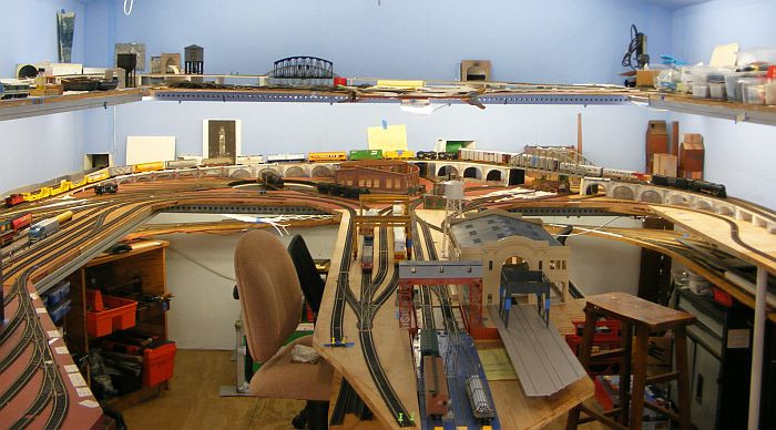
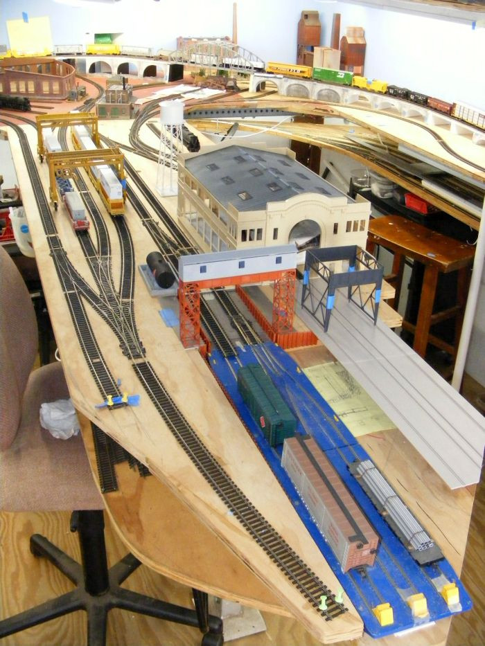
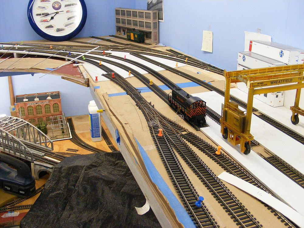
Interesting track plan, Tupper Lake & Faust Junction


Wiring My Roundhouse Tracks

Working my way around the layout.
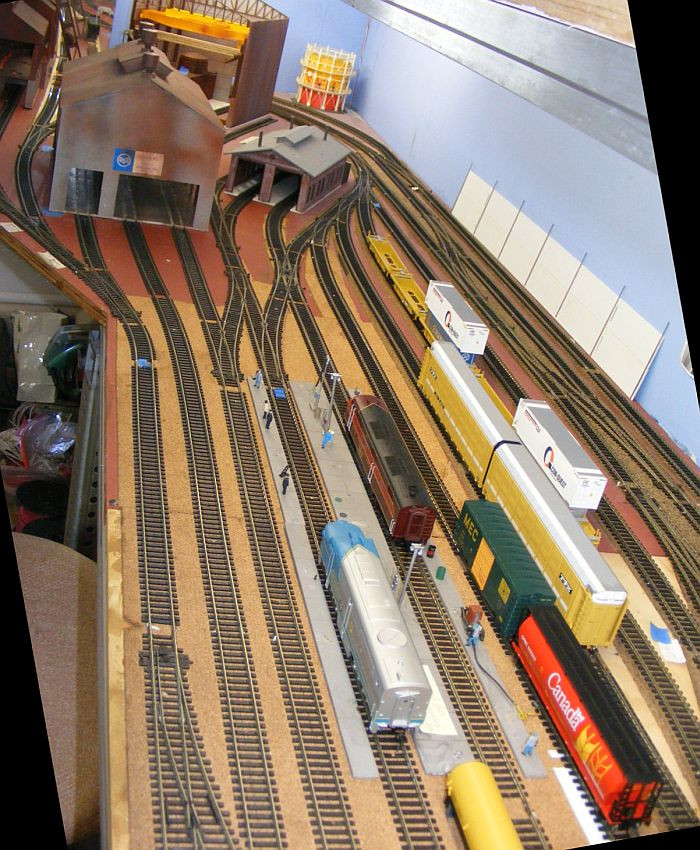
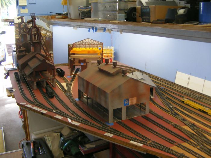
I have mounted my incomplete roundhouse on a thin metal base plate for several reasons..


image-20210216231819-1.jpeg


image-20210216231932-2.jpeg


One of the primary reasons was so I could extract it at some later dates to finish it out ,...and to add additional details down the road. For that reason it needed its own permanent base with the internal tracks already installed,...so the whole structure including its tracks could be withdrawn and replaced, at will, in one chunk.


image-20210216232024-3.jpeg


Naturally I need to power those tracks within the round house, but I don't want to do it with individual feeders to each of those tracks,..too many connections/disconnections to make each time. So I'm thinking of ways to wire those tracks together such that I only end up with 2 wires actually going thru to the bottom side of the deck. I'm thinking I can run each polarity wire across the expanse of the five tracks, just under the rails and between the ties, then down thru a single hole in the plywood deck. My solid core, 22 gauge wire will fit just fine. That size wire should be just fine for powering those very short roundhouse tracks.

Does anyone see any problems with that 'series' hook up of feeders wires? Or does anyone have an alternative suggestion(s)??

I also believe I will connect one side of the feeder pair to a toggle switch such that I can turn the whole set of tracks off except when I want to move a loco.

(don't need all those locos just sitting their idling when not in use.) I'm thinking of doing the same toggle cutoff for those outdoor storage tracks as well.
 
from another forum...
Without each track being powered separately you will have all locomotives running at the same time. If they have sound , it could be annoying. I prefer to be able to turn on the track I need.

Couldn't most of them be silent except when addressed specifically?
I have heard that they don't turn off completely if they are sitting on a powered track, but do they have to make noise (or move) if they have not been called on??
Any DCC loco, INC a DCC sound-equipped loco that is "sitting silent",
is still drawing some ammount of power from the rails.
(Maybe not as much per-loco as when hauling a heavy train upgrade with "Full Noise = ON", but some...
...just like a computer which is "in Standby mode", as opposed to being explicitly turned OFF),

This is why the reccomendation for "DCC layout power distribution planning" often includes setting up roundhouses and engine-terminals with their own breaker, if not their own discrete Booster.

The idea is simply that these locations will be where a lot of locos will congregate ,
and thus that location will demand a comparatively lot of cumulative power/current on "layout power-on",
as all the locos in the roundhouse/terminal try to "power up" simultaneously...

(Flipside, if a short happens somewhere "in the terminal",
where a lot of short-inducing loco movements might logically occur,
the breaker/booster will take-down and thus protect only the terminal,
leaving the rest of the layout Alive-and-Still-Running...)

The answer is, it depends on the decoders and sometimes their settings.
Behavior like you ask is not standard. Partly because some people and
vendors like the loco to respond right away and others like to go for the
more prototypical where you have to do things to wake it up.
How the vendors give you options about this are not standard either. You
will either have to look into the datasheets for the decoders or use
something like JMRI to figure out how to adjust the loco behavior to the way
you want it.
If someone had not properly stopped a loco before you turned off the power
may leave it in the command station with functions or speed still on. If
power is applied to that loco, it will respond.
The static drain of decoders is very low. The idle sounds of a decoder
consumers more power as would lights. One downside of using a single circuit
for all the round house tracks is the inrush and startup hit all those
decoders would get every time you turned it on to get one of them. Same
issue with power down, some particularly with keep alive may make some
really weird sounds as they discharge after you turn off the track.
My normal suggestion is either leaving the tracks live or wire for
individual control of each track.
-Ken Cameron, Member JMRI Dev Team


I was looking this situation over again today, and arrived at new KISS ideas.

First off I am going to power each track individually as has been suggested. I will attach two feeders wires to each of the 5 roundhouse tracks,...somewhere along those tracks where we might find pits between the tracks (thus hiding those track connections with some sort of pit image glued between the rails).

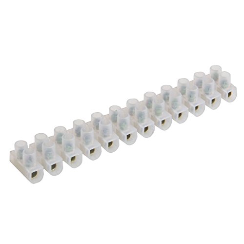
Those 10 feeders will go down thru the plywood deck in generous size holes that will also be hidden by the 'pit image'. Those feeders will be attached to a wire-to-wire terminal strip like this..
Terminal Block Connector Strips | The Tools & Fixings Co.


China 3A 2 Way Screw Terminal Block Connector - China 2 Way Terminal  Connector, 2 Way Terminal Block


When it is desired to remove the structure for detailing it will simply be unscrewing those 10 wires and letting them come up with the structure and tracks as a whole unit. Upon replacement the 10 wires will be fed back thru the holes in the plywood deck, and rescrewed into their terminal spot.

I'll be providing a terminal block for both polarity feeder wires. One polarity will be wired as a 'common wire' and the other will be individually fed to a cut off switch such that each individual track can be cut off or powered up.

I will also be wiring up my other stowage tracks around the perimeter of the turntable in a similar fashion so that each of them can be powered up individually. I have a fair number of them, and I may resort to using a single switch to control 2 tracks rather than just 1.


image%28127%29.png


image-20210223201827-1.jpeg
 
Been quite some time since I posted to this particular subject thread. Lets bring it up to date,..

Sep 11, 2020

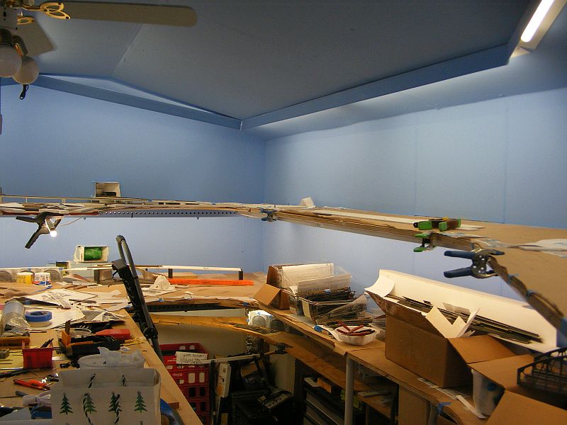
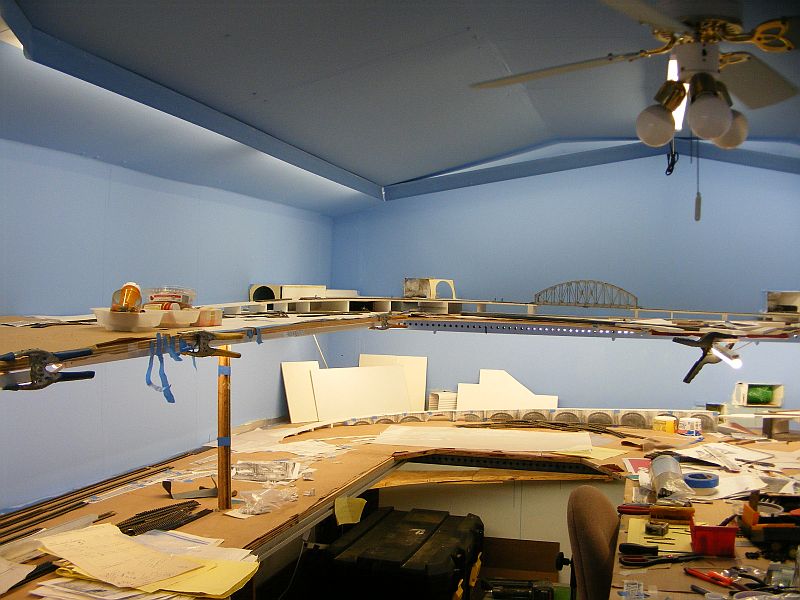
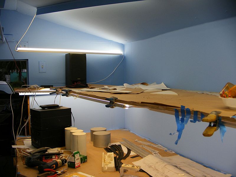
New Sky Colors & new LED lighting
Sorry for the working bench atmosphere.
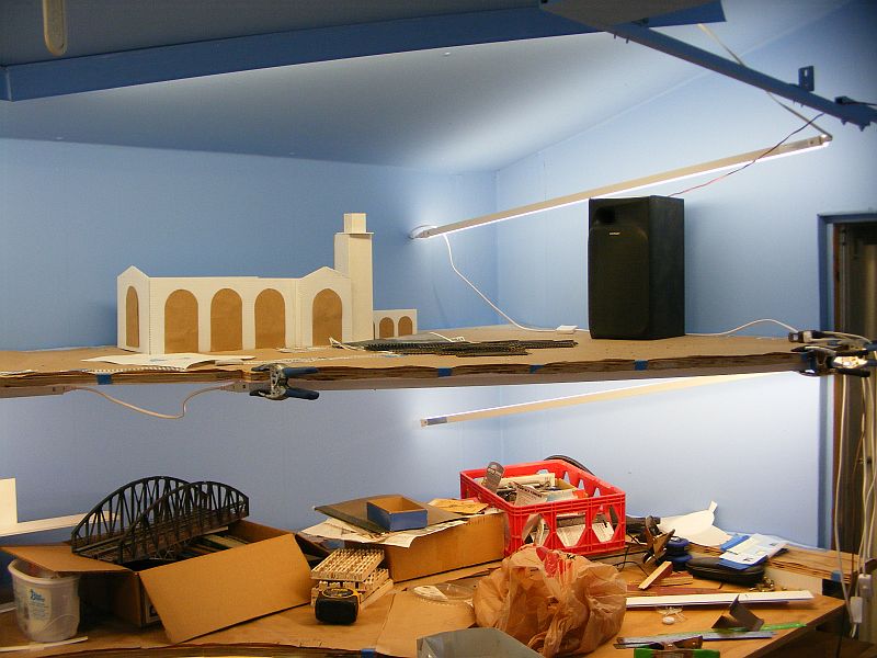
Here are some photos of my blue sky finish (a flat blue color called Autumn Sky) along with the LED tube lights. There are 2 on the upper ceiling at that one end that are still undetermined about their ____.
I took these without any flash, so the ceiling appears darker than it really is.
02837-1.jpeg


02921-2.jpeg

03017-3.jpeg

03109-4.jpeg
 
Transcontinental Theme
I knew I only had just so much space in my train shed, and like my previous Central Midland layout I wanted maximum number of industries included. My thoughts were that heavy industrial areas had rather a lot of tracks in them. So I would have one rather heavy industrial area on my lower deck, then another on my upper deck. The rather long track in the helix would represent the distance across the country from the west coast (California) to the east coast (Balt).

This transcontinental theme resulted from my desire to have considerable rolling stock (and engines) from Santa Fe and B&O, C&O. That thought had first surfaced back on my Central Midland layout and just fell right over into my new layout. I had also become aware of the significant amount of containerized traffic that carried Asian goods across the country prior to any expansion of the Panama canal. So that became one of my primary themes, getting container trains from their west coast port to an east coast port.
Click to expand...


I have a new way that I am looking at my current layout plan. Some folks have talked about allowing 'open spaces' between towns, and even industries, so things don't look so crowded.

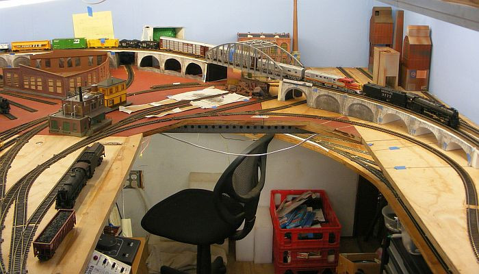
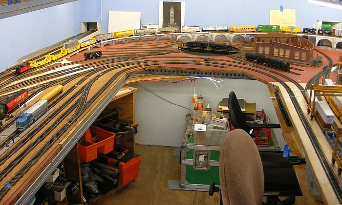
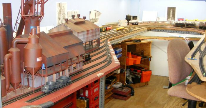
I was looking at the bottom deck of my layout yesterday, and what I was seeing was all Baltimore. It is the compact industrial area of Baltimore, the turntable/roundhouse, the coaling station, the freight yard, the steel mill, the waterfront village, the brick factory, cement silos, the coke plant, the power station, the container port, the carfloat, the stone arch viaduct, etc. Most all these industries were found in Baltimore at one time.
https://forum.mrhmag.com/post/spaghetti-bowl-layoutstrackplans-12219370?pid=1331408380
my present day lower deck
1.jpg
That left lower corner is going to be Balt city scene built using flats,...and note that is the Bromo tower. Over on the left wall there will be a image of Mt Royal train station. And the viaducts are representative of the infamous Thomas viaduct

2.jpg

3.jpg

and of course steel was a a big part of Balt's history,...Sparrows Point

4.jpg

5.jpg

6.jpg

7.jpg

8.jpg

9.jpg


I know, I've heard it over and over again,...10 lbs of stuff in a 5 lb bag. Its been a challenge to design and get radi big enough for long steamers, AND actual switching operations.
 
So I have pretty much firmed up all of my track laying for the bottom deck.

Now I have moved up to my top deck,...where i had a lot of the track plan 'mocked-up',..but it needed the final touches. These final touches can be quite time consuming as well, particularly when I am working somewhat in slow motion.
I started on refining the Refinery area, which joins with the cryogenic area. The i also expanded the helium area.
https://forum.mrhmag.com/post/cryogenic-plant-helium-plant-12213985?pid=1331857358

[DSCF7536]


I had changed things from a single mainline to a double mainline behind the refinery, and needed to make sure i had some good radius in those mainline, as well as disguising them with the refinery images,..
[DSCF7608]


Then I needed to coordinate those tracks with the helium and cryogenic areas,..
https://forum.mrhmag.com/post/cryogenic-plant-helium-plant-12213985?pid=1332135816

I've even provided several tracks where a switcher engine can reside than can handle multiple car movements within this refinery-helium-cryogenic complex.
[DSCF7669]
 
One thing leads to another. Next i had to refine that coal mine area (just up from the cryo area) , and the exit/entrance tunnel to the helix loop.

I screwed up !!

Today I was working on this particular corner where I had (have) plans for the coal mine. I am using the Wathers New River Kit, and I thought I had it all thought out as to how it was going to rest on some foamboard I had fashioned to cover the 2 mainline helix tracks running under it.
For some reason I fashioned that foamboard in 2 levels rather than just one,...I don't know why I did that. The problem now is that the 3 tracks under the loader are now at least 1+3/8" too low. It would be nice it I could replace that double level foamboad with a single level one, BUT that would screw up a couple of things,..1) I can't go lower as I need the higher level in order for double stack cars to run on those mainlines beneath it, and 2) I can't go to the higher option as I can't make the access tracks that steep.

What are my options? Do I dare to try and cut (section) that mine kit down by perhaps 1.25",...or ??

DSCF7662.jpg DSCF7661.jpg


https://forum.mrhmag.com/post/new-river-coal-mine-modifications-12292633?pid=1332050522

https://forum.mrhmag.com/post/new-river-coal-mine-modifications-12292633?pid=1332054414

[51558972964_991e89a9e6_z]


My coal mine building need to be a little higher over its tracks in order that the helix dbl tracks underneath could carry dbl-stack cars, ...the solution was to add coal chutes to new River Mining Kit,.......like this (not done yet but definitely in my plans)
 
Last edited:
Here is one of the idler tracks for a switcher that would very actively work the cryogenic tracks, the helium tracks, and the refinery tracks,..
[DSCF7669]

There is also another long spur behind the refinery that would allow both a switcher,...and multiple oil and propane cars to wait for their turn at the loading racks, or wait to be added onto a parting mainline train.


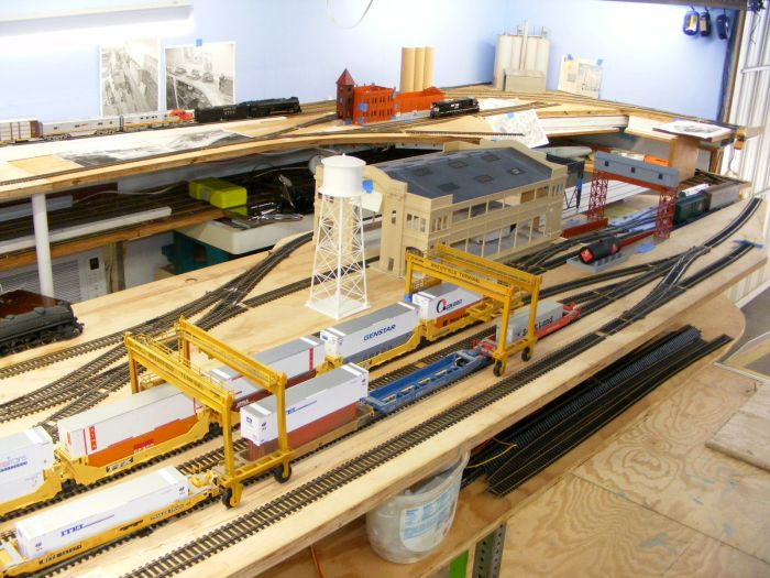
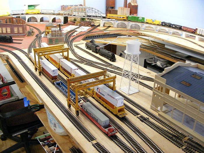
Over in this other corner on the upper deck is space I am working on at this time. Most importantly it is the entry/exit tracks for my west coast container yard. Mostly this is where the containers coming off the ships are stacked up, and subsequently trucked out to the 2 traveling cranes that load up the waiting rr cars. These cars are shuffled in and out of the loading tracks by 1, maybe 2 switcher engines that can be idilled on that long stub track;...
DSCF7716.jpg


There is also another switcher that works the logging saw mill, AND the lumber mill over there in the corner. There are several places where this switcher can idle. This switcher is keep real busy with multiple task around saw mill with cuttings removal, moving raw sawn timbers onto cars of mainline trains, and moving sawn lumber over to the factory owned finishing mill in the very corner. That corner will have stacks of lumber drying out, and stacks of lumber that has been milled and waiting for loading into/onto Thrall all-door cars and Centerbeam cars.

That little saw mill switcher will be kept pretty busy. ( I was hoping to make use of this little guy for some of that duty,..
https://forum.mrhmag.com/post/044t-...?highlight=0+-+4+0t+locomotive&pid=1331309287
 
WOW, I finally got to run a couple of locos on my upper deck,....not all the way around yet, as I have not built that double track bridge that will go across the entrance-way. But I did run those locos from one side of the bridge back around to the other side.

And this was done with a single DC transformer, and NO dcc connections such as feeder wires, and buse wires. Obviously I must have gotten most of my tracks soldered together well enough to transmit the power thru the rails. I only hooked up the DC transformer to the tracks to either side of the entrance way.
 
Have you checked the fouling distance for the switcher on the idler track leading to the cryo tower? Looks like you might need to add at least another inch of track. Perspective of the photo might not show that it has enough clearance when it actually does.
 
railandsail wrote:
Mirrored Power Plant?
Just for the fun of it I thought I might play with the idea of a mirror image on the power plant to see if i could make it, and its piles of coal look larger?

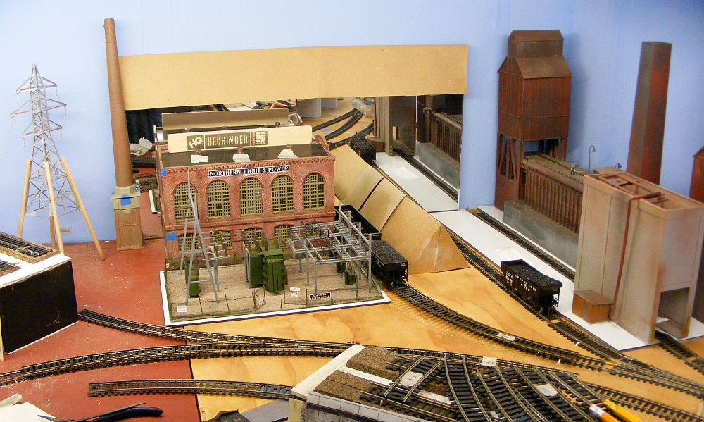
First I just placed a piece of mirrorized tile in the background (please ignore the fact that it has a decorative finish on its mirror). Of course it is reflecting an image straight up my aisle so I had to make an attempt to block a portion of that with just plain white paper folded over a portion of the mirror.
Then I had to attempt to block out the reflected image of the coke plant,..again with pieces of paper blocking those portions.

Then I wanted to include the piles of coal needed by the power plant,...those plastic tubs.

I was thinking this rather unusual shaped reflective surface might be attainable utilizing mirrorized mylar foil?
DSCF5498.JPG
DSCF5499.JPG
I'm now thinking this image of a bigger plant and piles of coal would be better obtained with some sort of artist/photo shopped image pasted on the backdrop.

Perhaps I really need to explore this Affinity Photo technology more thoroughly.
https://forum.mrhmag.com/magazine-feedback-was-ezines-891776


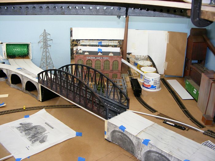
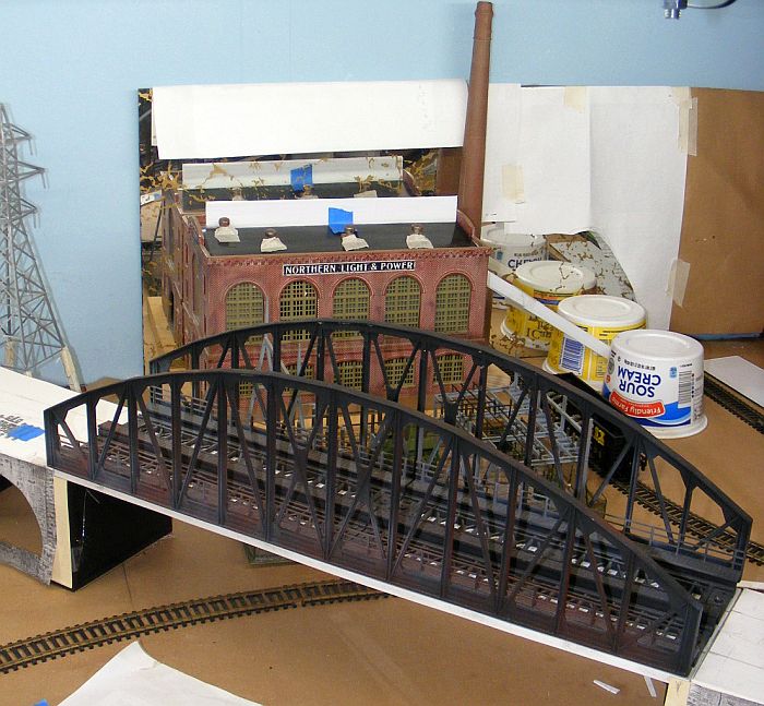
Quite far back in this subject thread I was playing with ideas for the power plant and the coke plant that are located back in a corner behind my viaduct bridge. In the past I had taken this particular bridge out and replaced it with another very similar one that had the proper track spacing,...but it was grey/silver in color. Just yesterday I took that newer bridge out to paint it black like this original one.

https://forum.mrhmag.com/post/steel...oke-plant-power-plant-12209837?pid=1331351657

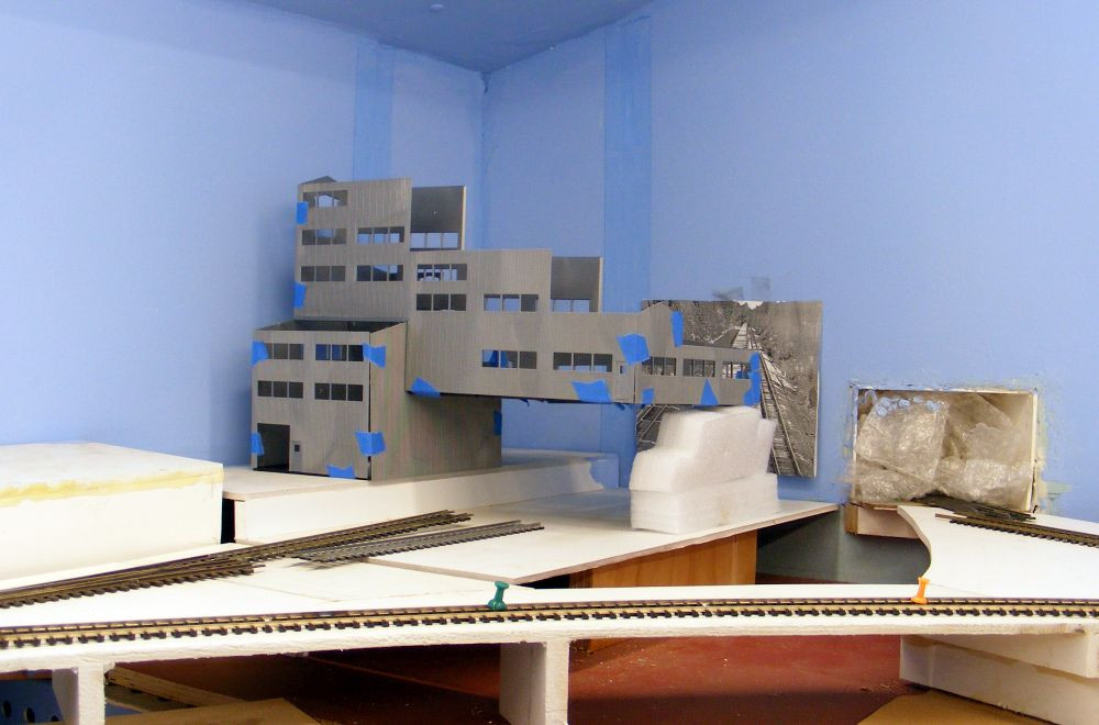
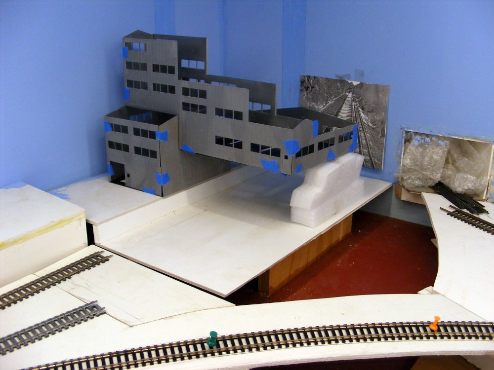
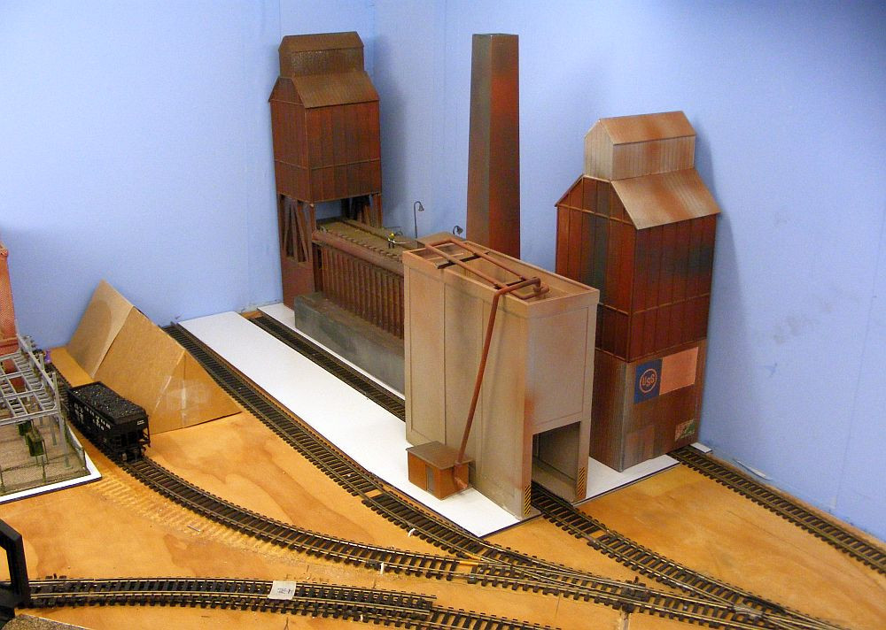
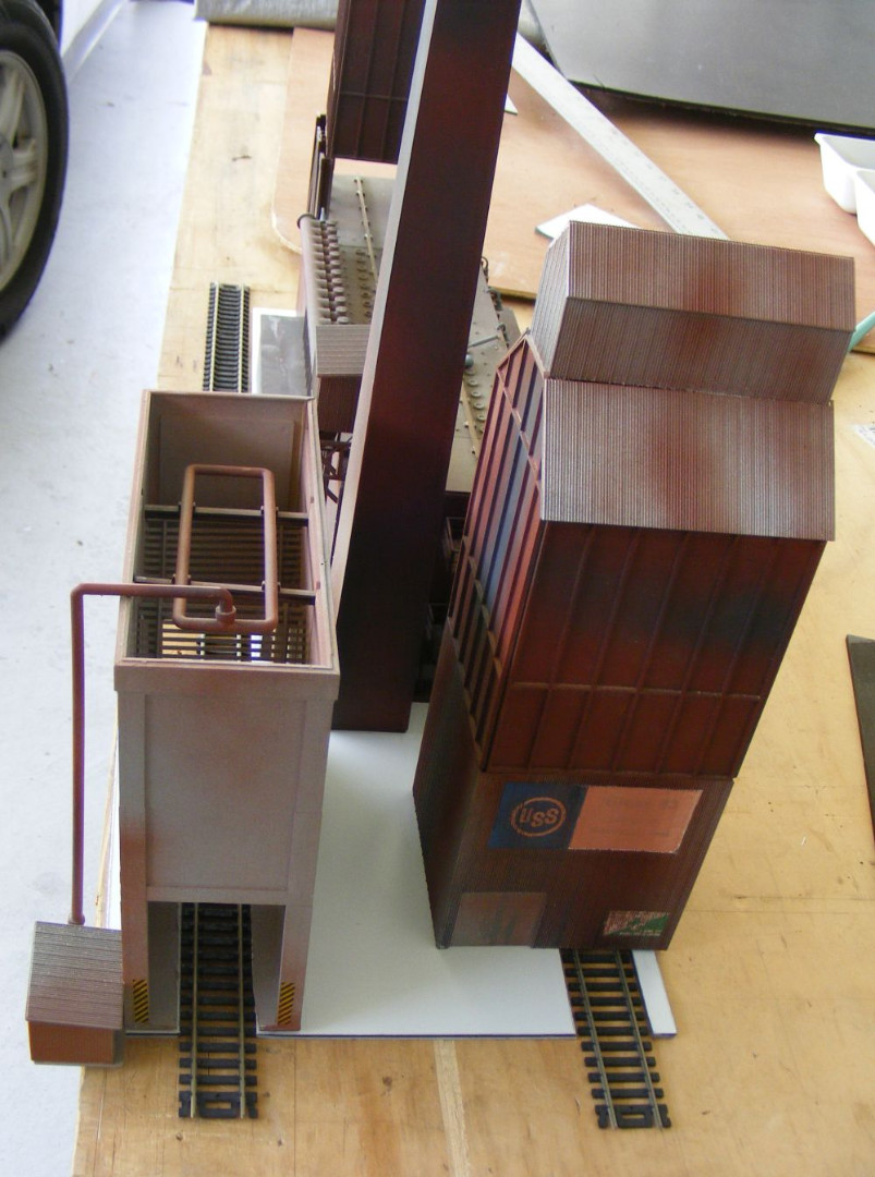
While I had the bridge out I decided to do some more work on those structures back there (power plant & coke plant). One of the primary additions I wanted to make at this time was to construct 'base plates' for those structures so they could be removed as entities in the future for extra detailing work off the layout. In other words I do not have the time at the present moment to do that extra detailing but hopefully will have time after I get the whole layout up and running.

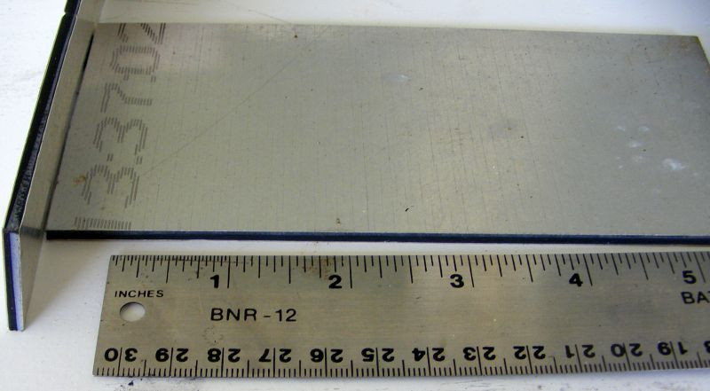
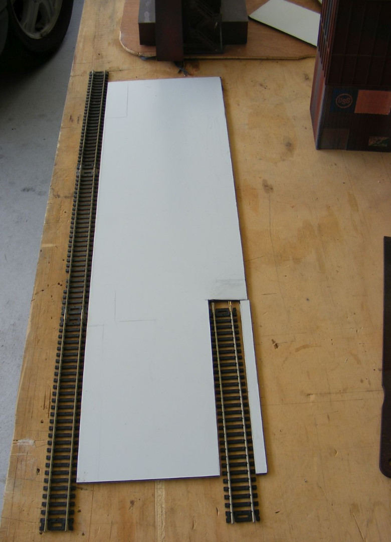
Naturally I am concerned about reaching over that bridge and viaduct structure to do any detailing on those structures behind it. I wanted to attach those two structures each onto a 'base plate' so they could be lifted out to be worked on in a separate area. I had some relatively this stiff plate material I had savaged from my local sign shop. It is a sandwich structure of these alum skins on a foam core,..
0.11" thick sandwich material..
DSCF7943.jpg


Surprisingly it can be cut with a number of passes with a sharp box cutter. I didn't want the tracks servicing these plants to be mounted on these bases as that might complicate things. So I cut those base plates such that they will 'surround' those tracks that will be mounted permanently to the deck.
DSCF7938.jpg

DSCF7932.jpg

DSCF7933.jpg


I also moved the power plant over a bit further from the viaduct in order to possible insert another track ,...I know, I know,...another track!!! (details possibly soon 😵
 
That piece of white base material between the 2 tracks will be made into a 'coke wharf'

I intend to relocate the pump house for the quenching tower to a more center position, AND likely will make a larger diameter pipe to feed the tower. After all these quenching towers used LOTS of water from what I understand.

The tent like cardboard structures there are just initial ideas for coal piles for the power station. I need to do a bit more experimenting on the mirrored backgrounds,....perhaps some reflective mylar?
 
One Thing Leads to Another, ...Then Another,... Etc

I guess part of my frustration is I am real close to completing the wiring for my upper deck,.... at least enough to get some trains to run completely around it, AND down my helix to the lower level. Wow, I would feel like I was really making progress.

BUT as I was wiring up my bus wiring for that upper deck, I decided I needed to move that viaduct bridge out of the way so I didn't damage it while working on the under side of that upper deck. Concurrently I knew I want to consider painting that bridge a different color,...so off onto another tangent. Then while I had that bridge out of the way, why not do some more work on those 2 structures behind the bridge. Now I am once again bogged down with how I might want to place the mirrors behind the power plant, so yesterday I spent a few HOURS looking at stores where I could find some mirrored surfaces,...perhaps a mirrored Mylar film rather than mirrors themselves,..without a great deal of success.

Long story short, I let all these 'distractions' get in the way of completing my wiring of the upper deck,..and test running a few trains up there.....the source of some of my frustrations!

PS: Then of course I need to fit in an afternoon nap that I seem to need more often these days
 
Last edited:
Playing with Mirrors

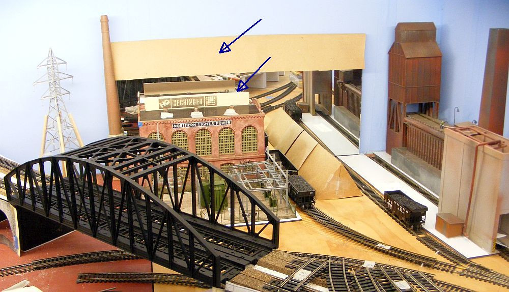
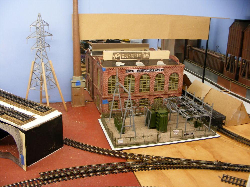
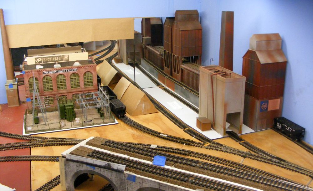
I did some more playing with the mirror idea in this corner. I did manage to find a set of just plain 12x12 frame-less mirrors to experiment with. As a result I am overlapping them, and blocking out portions of them with brown paper I had used to draw out my track plan full scale.

My primary desire was to make the power plant appear to be larger,...double in size. And correspondingly to make their coal supply piles bigger, along with the string of coal cars that bring in that coal.
DSCF7944.jpg

DSCF7945.jpg

DSCF7948.jpg
I've blocked off the upper portion of the mirror at that point so I just see the 2 roofs of the double power plant, and I added a sign (just a paint stir at this time) atop the roof to further block the reflection of the track and bridges out front. You will see these images, but they will be subdued (overwhelmed ) by the power plant and electrical distribution field.

I played with the location of the chimney for the power plant,...wanting to have 2 (but not so easy), and with which side to place it on. Right now I like the left side, with some separation from the building itself to give a better view of the dbl-sides of the plant,...better depth image?


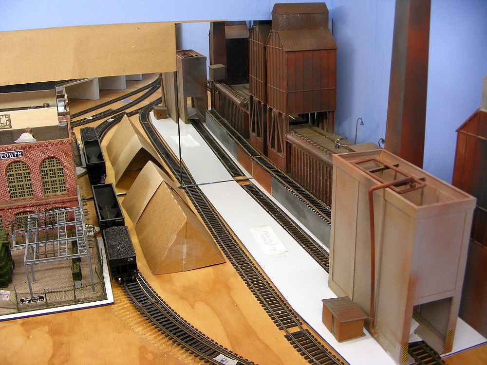
In order to get the coal piles and coal cars into the 'double image' , the reflection displays a portion of the coke plant. So I began to consider a double image of the coke plant as well,...by extending the mirrors over to the corner of the room,..
DSCF7946.jpg

DSCF7947.jpg


I'm beginning to like the double coke plant,..really makes the corner piece of the layout look quiet extensive. And I believe I have seen a number of real life coke plants that were lined up something like this??

I would likely make the mirror slightly taller over there to include dbl-image of the coaling tower, and dbl image of the quenching unit and the coke furnace discharge side

And yes the dbl viaduct tracks do show up, but I think they are over-powered by these two structures filling up that corner real estate??
 
One problem with mirrors is the fact that the reflective surface is on the back, so any reflection has an .125"-.375" gap depending on the thickness of the mirror itself. Using some kind of reflexive Mylar would solve that issue. They do make what's known as front reflexive mirrors, (sometimes called first surface mirrors) but the last time that I checked, they were quite expensive.
 
I had heard of those type mirrors, and also that they were quite expensive. And my application (custom shaped) might end up being that much more expensive.

So I think I will just stick with std thin mirrors unless I locate some good reflective Mylar at a good price. BTW I did see some auto window tinting material that was very thin and reflective,...but also expensive.
Go into a 'grow shop' and you should find reflective Mylar. Pretty thin stuff and will tear easy although in your application you can attach it to a background stiffener board of some sorts. Could get you what you want. If I remember correctly, the roll of Mylar I got was pretty cheap.
 
HI Brian,
At Port Kembla we had 6 coke ovens batteries lined up in a line. The #1, the earliest dated from 1939. In the early 1970's I started my career in steel on #3 battery built in the 1950's. #4 to #6 batteries were built much later, with #6 battery built in the late 1960's . Currently #4, #5 and #6 batteries are still running. #1 & #2 have been demolished. The remains of #3 still stand but all the ancilliary equipment (rams, extractors, hot cars etc and I'll bet most of the electrics and instrumentation) has been removed for re-use r scrapping after the battery was shut down.

So yes your reflection idea can work for coke oven batteries "lined up in a row".

Regards,
John Garaty
Unanderra in oz
 
One problem with mirrors is the fact that the reflective surface is on the back, so any reflection has an .125"-.375" gap depending on the thickness of the mirror itself. Using some kind of reflexive Mylar would solve that issue. They do make what's known as front reflexive mirrors, (sometimes called first surface mirrors) but the last time that I checked, they were quite expensive.
Willie is right. Front surface mirrors are spendy. They typically are used for laser setups. There is still refraction with the front surface mirror although not as much as a ...um... normal mirror. Light bends going in and bends again going out so keeping the beam in focus and a pin-point is trouble.


Back
Top