
You are using an out of date browser. It may not display this or other websites correctly.
You should upgrade or use an alternative browser.
You should upgrade or use an alternative browser.
DSD's Layout Progress Thread
- Thread starter DairyStateDad
- Start date
ModelRailroadForums.com is a free Model Railroad Discussion Forum and photo gallery. We cover all scales and sizes of model railroads. Online since 2002, it's one of the oldest and largest model railroad forums on the web. Whether you're a master model railroader or just getting started, you'll find something of interest here.


You know, you're right -- I took a second look and realized there isn't the amount of room there that I thought there would be. I'm going to give it some more thought, but I appreciate the feedback.
I was also beginning to wonder about this because the runaround I have put in isn't in the right place, but on the other hand I can't make it fit in what would be the right place.
If I do stick with the original approach -- one thing I'm realizing is that I will want to get started on the upper level much sooner than I had originally contemplated. I think one big reason this other idea captivated me was that I am itching to get that focal point started, too...
Also, still interested in other feedback if it's out there to be given!
Ya know, I'm coming back around to the original, too. (This has happened a few times now -- I've been certain about the overall design, get some idea for tweaking it considerably, spend about a day trying to develop the alternative approach, then decide it doesn't work after all... maybe it's an ADHD thing )
)
Looking back on the flurry of activity I put into the abandoned re-design in the last 48 hours or so... I think that it got me so wound up because I am really eager to get to that upper level... So I'll just need to move ahead with all deliberate speed to get to that point.

No, I redesigned that. There will be two, and eventually three, independent tracks over that area, but the staging yard does not extend to it
I redid the yard significantly just as I was putting in cork earlier this year. More on that here: http://www.modelrailroadforums.com/...-s-Layout-Progress-Thread&p=341472#post341472
That was one of those late revisions that actually *Was* an improvement and so I stuck with it!

My first reaction was, 'but that won't work -- the plywood is only 1/4-inch luan' -- which it is because of a very long story that I'll explain in another post.
But then I realized... Yes, but the cross braces (on 24 inch centers for this section -- that's part of the very long story) are 3/4-inch plywood (instead of dimensional lumber).
Which means if I wanted to I could screw or bolt vertical supports to them! I would just cut through not only the foam but also the luan underneath it to make slots for the uprights to come through. I never thought of that until your post, gator -- so thank you!
That would be a bit more work, but I think it might be worth it. I will ponder that some more...

Affiliate Disclosure: We may receive a commision from some of the links and ads shown on this website (Learn More Here)

DairyStateDad
Mumbling in the corner
Thanks, Louis.... 
DairyStateDad
Mumbling in the corner
Ruh-rohhh....
OK, so as I'm moving along and getting ready to install more track, I get this sudden idea...
What if...
Instead of putting Eagle Junction [Yellow track] on the upper level above the staging loop [Blue Track]
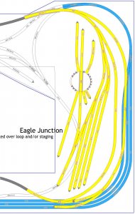
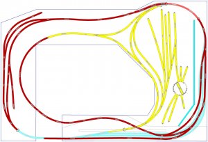
I incorporate the Eagle Junction yard inside the loop on the lower level... (Yellow Track) and reduce the hidden area considerably to just the double-ended staging yard... (Blue Track) the EJ yard would be a bit smaller, to be sure, but not that much... and Eagle Junction trackage would include the Wye (which when it was first conceived as seen as part of St. Matthew)
Something like this...
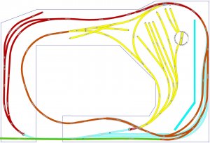
Then the upper level would just be a narrower part that is right over the staging tracks... (and visually blocked, sort of, from Eagle Junction by a double-sided backdrop -- removable so that for operation I could see everything from the center pit if I'm by myself).... There would be a simple passing siding there, and that becomes St. Matthew...
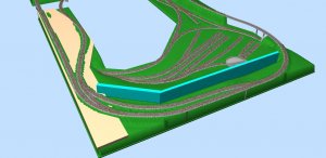
The basic twice around track configuration would be about the same, except for that.
Trains would start at Eagle Junction (formerly St. Matthew) -- Yellow Track -- (or off-stage from there -- blue track ), run up the hill counterclockwise (Brown Track) through St. Matthew (formerly Eagle Junction) and down to Aaronsburgh, (formerly Aaronsburgh) and back to staging.
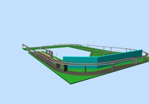
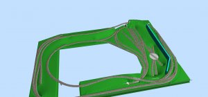
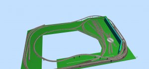
[Here's the 3D View without terrain, so you can see the staging tracks underneath)
Totally crazy?
OK, so as I'm moving along and getting ready to install more track, I get this sudden idea...
What if...
Instead of putting Eagle Junction [Yellow track] on the upper level above the staging loop [Blue Track]
I incorporate the Eagle Junction yard inside the loop on the lower level... (Yellow Track) and reduce the hidden area considerably to just the double-ended staging yard... (Blue Track) the EJ yard would be a bit smaller, to be sure, but not that much... and Eagle Junction trackage would include the Wye (which when it was first conceived as seen as part of St. Matthew)
Something like this...
Then the upper level would just be a narrower part that is right over the staging tracks... (and visually blocked, sort of, from Eagle Junction by a double-sided backdrop -- removable so that for operation I could see everything from the center pit if I'm by myself).... There would be a simple passing siding there, and that becomes St. Matthew...
The basic twice around track configuration would be about the same, except for that.
Trains would start at Eagle Junction (formerly St. Matthew) -- Yellow Track -- (or off-stage from there -- blue track ), run up the hill counterclockwise (Brown Track) through St. Matthew (formerly Eagle Junction) and down to Aaronsburgh, (formerly Aaronsburgh
) and back to staging.[Here's the 3D View without terrain, so you can see the staging tracks underneath)
Totally crazy?

DairyStateDad
Mumbling in the corner
Just as a point of clarification... the blue section isn't lift out, but it is hidden. Unfortunately it's not very visible in the renderings above. Here's another picture of it alone, without showing the track that is above it.

The yard at Eagle Junction in the new version is very, very rough -- there's probably a lot I would do differently with it if I put some more time into the details. At the very least it needs a runaround somewhere, I think.
I've been pondering why I even find myself suddenly drawn to this fairly major modification. Part of it is that I'd like to get the visible yard going sooner, which if it's on the upper level it won't. Part of it is that whatever is on the upper level has to be able to be lifted off to allow full access to the track underneath, and making the entire 3-x-8 foot upper level a lift-off section strikes me as an engineering nightmare. And part of it is that while eventually the staging track would be hidden by upper level track even with the new design, it could be exposed for a lot longer, allowing me to make sure it's really functioning well.
The yard at Eagle Junction in the new version is very, very rough -- there's probably a lot I would do differently with it if I put some more time into the details. At the very least it needs a runaround somewhere, I think.
I've been pondering why I even find myself suddenly drawn to this fairly major modification. Part of it is that I'd like to get the visible yard going sooner, which if it's on the upper level it won't. Part of it is that whatever is on the upper level has to be able to be lifted off to allow full access to the track underneath, and making the entire 3-x-8 foot upper level a lift-off section strikes me as an engineering nightmare. And part of it is that while eventually the staging track would be hidden by upper level track even with the new design, it could be exposed for a lot longer, allowing me to make sure it's really functioning well.
DairyStateDad
Mumbling in the corner
Refined the plan for Eagle Junction a little more....
DairyStateDad
Mumbling in the corner
Sooo... Like at the eye doctor's:
This?
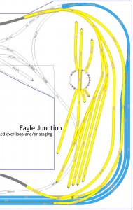
Or this?
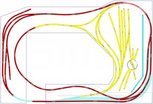
This?
Or this?
logandsawman
Northern Pacific history enthusiast
I like the top one. I think with all the track in the bottom one if you put some other stuff in there like buildings or roads or anything it will feel crowded.
lasm
lasm
DairyStateDad
Mumbling in the corner
I like the top one. I think with all the track in the bottom one if you put some other stuff in there like buildings or roads or anything it will feel crowded.
lasm
You know, you're right -- I took a second look and realized there isn't the amount of room there that I thought there would be. I'm going to give it some more thought, but I appreciate the feedback.
I was also beginning to wonder about this because the runaround I have put in isn't in the right place, but on the other hand I can't make it fit in what would be the right place.
If I do stick with the original approach -- one thing I'm realizing is that I will want to get started on the upper level much sooner than I had originally contemplated. I think one big reason this other idea captivated me was that I am itching to get that focal point started, too...
Also, still interested in other feedback if it's out there to be given!
DairyStateDad
Mumbling in the corner
I too prefer the top design Erik, but which ever you run with, it is going to be an interesting build.
Ya know, I'm coming back around to the original, too. (This has happened a few times now -- I've been certain about the overall design, get some idea for tweaking it considerably, spend about a day trying to develop the alternative approach, then decide it doesn't work after all... maybe it's an ADHD thing
)Looking back on the flurry of activity I put into the abandoned re-design in the last 48 hours or so... I think that it got me so wound up because I am really eager to get to that upper level... So I'll just need to move ahead with all deliberate speed to get to that point.
DairyStateDad
Mumbling in the corner
Constructing a removable panel of track with wiring included.
So I'm back to thinking about how to construct that upper level if I stick with the yard up there.
It needs to be as thin as possible. I want it to be easily removed (for lower level access), but for the most part it won't actually be removed that often I hope.
I want to optimize sturdiness, low profile, simplicity and weight.
While it would be tempting to do one 3-foot-by-8-foot segment, I'm thinking I'll have to break it into two 3x4 segments. (But I might start by trying to make it a single 3x8 segment and see if I can handle it that way.)
My first instinct is to use a 1/2-inch underlayment of MDF, topped with a piece of 3/4 inch or 1 inch foam. I think I might run corner moulding all around it (from the underside) to create a sort of frame.
--UPDATE: Methods and procedures completely Revised. Disregard the remainder of this post (other than for historic purposes)

I would use plastic wall conduit or raceway to organize the bus wires for the track and the turnouts on the underside of the MDF.
And that would basically be it.
It would be supported by a series of pillars made of stacked layers of foam. I'd especially want to put some of those pillars as close to the corners of the underside as possible. but there would also be more in the center -- potentially any place where there isn't track on the lower level.
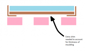
Because the top of the underside is foam, I can't really screw or bolt in wooden uprights for support, I don't think.
So does this sound adequate? Sturdy and stable enough, you think?
I'd probably have to work out additional details so that it stays still -- pegs or brackets or something.
So I'm back to thinking about how to construct that upper level if I stick with the yard up there.
It needs to be as thin as possible. I want it to be easily removed (for lower level access), but for the most part it won't actually be removed that often I hope.
I want to optimize sturdiness, low profile, simplicity and weight.
While it would be tempting to do one 3-foot-by-8-foot segment, I'm thinking I'll have to break it into two 3x4 segments. (But I might start by trying to make it a single 3x8 segment and see if I can handle it that way.)
My first instinct is to use a 1/2-inch underlayment of MDF, topped with a piece of 3/4 inch or 1 inch foam. I think I might run corner moulding all around it (from the underside) to create a sort of frame.
--UPDATE: Methods and procedures completely Revised. Disregard the remainder of this post (other than for historic purposes
)I would use plastic wall conduit or raceway to organize the bus wires for the track and the turnouts on the underside of the MDF.
And that would basically be it.
It would be supported by a series of pillars made of stacked layers of foam. I'd especially want to put some of those pillars as close to the corners of the underside as possible. but there would also be more in the center -- potentially any place where there isn't track on the lower level.
Because the top of the underside is foam, I can't really screw or bolt in wooden uprights for support, I don't think.
So does this sound adequate? Sturdy and stable enough, you think?
I'd probably have to work out additional details so that it stays still -- pegs or brackets or something.
Last edited by a moderator:
wombat457
I'm the one
Erik,
Sometimes our first inclinations are the best ones and the ones we tend to revert back to, especially when inundated with so many ideas and thoughts that it becomes little more than a confused frustrating mess, regardless of how good those ideas are and regardless of whether we think of them or they are offered or seen.
Sometimes our first inclinations are the best ones and the ones we tend to revert back to, especially when inundated with so many ideas and thoughts that it becomes little more than a confused frustrating mess, regardless of how good those ideas are and regardless of whether we think of them or they are offered or seen.
DairyStateDad
Mumbling in the corner
Do you still have multiple tracks on your crowl-under/ lift out? Think about using a gauntlet track. I would be concerned about having the yard extend on to the moveable section.
No, I redesigned that. There will be two, and eventually three, independent tracks over that area, but the staging yard does not extend to it
I redid the yard significantly just as I was putting in cork earlier this year. More on that here: http://www.modelrailroadforums.com/...-s-Layout-Progress-Thread&p=341472#post341472
That was one of those late revisions that actually *Was* an improvement and so I stuck with it!
gator do 65
Member
DSD,
If the lower layer of foam is on plywood just cut the foam out and use wood supports screwed or glued to the ply. this will also give you a sturdy place to install pins to locate the top.
If the lower layer of foam is on plywood just cut the foam out and use wood supports screwed or glued to the ply. this will also give you a sturdy place to install pins to locate the top.
DairyStateDad
Mumbling in the corner
DSD,
If the lower layer of foam is on plywood just cut the foam out and use wood supports screwed or glued to the ply. this will also give you a sturdy place to install pins to locate the top.
My first reaction was, 'but that won't work -- the plywood is only 1/4-inch luan' -- which it is because of a very long story that I'll explain in another post.
But then I realized... Yes, but the cross braces (on 24 inch centers for this section -- that's part of the very long story) are 3/4-inch plywood (instead of dimensional lumber).
Which means if I wanted to I could screw or bolt vertical supports to them! I would just cut through not only the foam but also the luan underneath it to make slots for the uprights to come through. I never thought of that until your post, gator -- so thank you!
That would be a bit more work, but I think it might be worth it. I will ponder that some more...
DairyStateDad
Mumbling in the corner
Followup --
I've been having a 'Well, DUH!' moment ever since I read Gator's post yesterday morning.
Some how the idea of cutting down through the foam and anchoring risers to the crossbars underneath the tops of the layout sections completely escaped me! And having now liberated that very simple and obvious idea, I've solved a bunch of other problems. Now I know not just how I'm going to support the Eagle Junction section over the staging layout, I know how I can easily support the two sided backdrop I want to put on one of the other sections.
I can't take time now but in between track laying I hope this week to get a start on both of those projects.
I've been having a 'Well, DUH!' moment ever since I read Gator's post yesterday morning.
Some how the idea of cutting down through the foam and anchoring risers to the crossbars underneath the tops of the layout sections completely escaped me! And having now liberated that very simple and obvious idea, I've solved a bunch of other problems. Now I know not just how I'm going to support the Eagle Junction section over the staging layout, I know how I can easily support the two sided backdrop I want to put on one of the other sections.
I can't take time now but in between track laying I hope this week to get a start on both of those projects.
DairyStateDad
Mumbling in the corner
Help me out -- Carpentry question
I have two basic ideas, and one variation (at least) regarding how the upper section (Eagle Junction) will be constructed.
The overall dimensions will be 3 feet by 8 feet. That's big, and I will build it as a single section. Not ideal, but there's too much track on it to try to make it into two segments.
The section will lift off of what is below it (staging track loop) -- but I emphasize, that will NOT be an everyday occurrence. it's mainly being set up that way so that a) if in an emergency I need more access to the underside staging loop than I will have (and I do plan for fairly easy access from the sides, with openings or even little hatches in the fascia), I can as a last resort remove the upper section. Also, this design from the beginning has been premised on being able to be moved to a new home. While that's not by any means certain ever to happen I wanted to be prepared for the possibility.
Clearance for the staging loop underneath will be tight -- no two ways about it. The total rise from ground level track on the layout to the topside of this upper section is 5 inches (maybe a little more, if I'm lucky). So I need to keep the upper section to no more than 2 inches deep, and less if I can manage it.
The upper section will rest on a series of benchwork risers. I will probably use pegs to hold it all in place. I've got that worked out quite thoroughly and I'm confident that it will be sturdy and stable.
Wiring will not be underneath the unit. Instead, I will have plastic raceway attached to the siderails and use that to carry the bus wires. I would like to figure out how to bury feeders to track and switch machine on the top of the layout in some manner. I have some ideas about that, but let's put those aside for now. The point is to make it possible to address wiring problems without having to work at the underside of the section. I also anticipate including some kind of plug connectors to link the upper unit's bus wire with the rest of the layout bus wire. Again, that's not a big issue in my mind, so put that aside.
Ok, I think that covers the basics. So for constructing the upper section, here are the options I now see.
Idea No. 1: Between the 1 x 2 side rails, I would run a series of 1 x 2 cross pieces, laid flat, each end screwed and glued to the side rails. Their bottoms would be flush with the siderails' bottoms.
I could put as many of these cross pieces in as I want -- anywhere from 12-inch centers to 18 inch centers. I would lean toward more -- ie, smaller centers -- rather than fewer cross pieces.
Atop the cross pieces would be a single sheet of 1/4 inch plywood, creating a sort of tray.
At this point, the tray itself would have only 1/2 inch of open space (the cross pieces would take up 3/4 of an inch, the plywood another 1/4 of an inch, and of course the 1 x 2 siderails are only actually 1.5 inches high). So the thickest foam I could use would be 1/2 inch. Cork, landscaping, track, scenery, etc. all would be built on the foam.
I could put a sort of 1/4 inch trim around the top of the siderails, giving myself another 1/4 inch in the tray, so I could use 3/4 inch foam instead of 1/2 inch foam.
VARIATION: I could skip the plywood and just put plain foam on top of the crosspieces. If the crosspieces are on 12-inch centers that should be fine, I think. . Then I would be able to use 3/4 inch foam to begin with, or if I add the trim atop the siderails, 1-inch foam. The cross pieces, not the foam, would be what comes in contact with the wood supports holding the whole structure up.
Idea No. 2: The other idea would be to skip the crosspieces entirely.
IN that case, I would start with a 3 x 8 foot sheet of 1/2 thick birch plywood. I would put the 1 x 2 perimeter frame on top of the plywood, nailed or screwed and glued. Then I'd have a full 1-1/2 inches depth in the 'tray' and could use a piece of foam that thick in there.
My biggest concern is that, this second idea makes the entire upper section a full 2 inches deep. So unless I'm willing to increase the grade up to the upper level, clearance on the underside would only be 3 inches -- or strictly speaking, 2-3/4 inches because of the cork roadbed on the lower level staging loop. I don't run modern cars with their high profiles, so it's probably doable, but I have trouble flouting the NMRA 3.5-inch-clearance standard.
SO: Does either of these particular approaches seem better or worse? Is there a third alternative I am not seeing?
Is there some other alternative -- which accommodates the specific points mentioned at the beginning -- that you would suggest?
I have two basic ideas, and one variation (at least) regarding how the upper section (Eagle Junction) will be constructed.
The overall dimensions will be 3 feet by 8 feet. That's big, and I will build it as a single section. Not ideal, but there's too much track on it to try to make it into two segments.
The section will lift off of what is below it (staging track loop) -- but I emphasize, that will NOT be an everyday occurrence. it's mainly being set up that way so that a) if in an emergency I need more access to the underside staging loop than I will have (and I do plan for fairly easy access from the sides, with openings or even little hatches in the fascia), I can as a last resort remove the upper section. Also, this design from the beginning has been premised on being able to be moved to a new home. While that's not by any means certain ever to happen I wanted to be prepared for the possibility.
Clearance for the staging loop underneath will be tight -- no two ways about it. The total rise from ground level track on the layout to the topside of this upper section is 5 inches (maybe a little more, if I'm lucky). So I need to keep the upper section to no more than 2 inches deep, and less if I can manage it.
The upper section will rest on a series of benchwork risers. I will probably use pegs to hold it all in place. I've got that worked out quite thoroughly and I'm confident that it will be sturdy and stable.
Wiring will not be underneath the unit. Instead, I will have plastic raceway attached to the siderails and use that to carry the bus wires. I would like to figure out how to bury feeders to track and switch machine on the top of the layout in some manner. I have some ideas about that, but let's put those aside for now. The point is to make it possible to address wiring problems without having to work at the underside of the section. I also anticipate including some kind of plug connectors to link the upper unit's bus wire with the rest of the layout bus wire. Again, that's not a big issue in my mind, so put that aside.
Ok, I think that covers the basics. So for constructing the upper section, here are the options I now see.
Idea No. 1: Between the 1 x 2 side rails, I would run a series of 1 x 2 cross pieces, laid flat, each end screwed and glued to the side rails. Their bottoms would be flush with the siderails' bottoms.
I could put as many of these cross pieces in as I want -- anywhere from 12-inch centers to 18 inch centers. I would lean toward more -- ie, smaller centers -- rather than fewer cross pieces.
Atop the cross pieces would be a single sheet of 1/4 inch plywood, creating a sort of tray.
At this point, the tray itself would have only 1/2 inch of open space (the cross pieces would take up 3/4 of an inch, the plywood another 1/4 of an inch, and of course the 1 x 2 siderails are only actually 1.5 inches high). So the thickest foam I could use would be 1/2 inch. Cork, landscaping, track, scenery, etc. all would be built on the foam.
I could put a sort of 1/4 inch trim around the top of the siderails, giving myself another 1/4 inch in the tray, so I could use 3/4 inch foam instead of 1/2 inch foam.
VARIATION: I could skip the plywood and just put plain foam on top of the crosspieces. If the crosspieces are on 12-inch centers that should be fine, I think. . Then I would be able to use 3/4 inch foam to begin with, or if I add the trim atop the siderails, 1-inch foam. The cross pieces, not the foam, would be what comes in contact with the wood supports holding the whole structure up.
Idea No. 2: The other idea would be to skip the crosspieces entirely.
IN that case, I would start with a 3 x 8 foot sheet of 1/2 thick birch plywood. I would put the 1 x 2 perimeter frame on top of the plywood, nailed or screwed and glued. Then I'd have a full 1-1/2 inches depth in the 'tray' and could use a piece of foam that thick in there.
My biggest concern is that, this second idea makes the entire upper section a full 2 inches deep. So unless I'm willing to increase the grade up to the upper level, clearance on the underside would only be 3 inches -- or strictly speaking, 2-3/4 inches because of the cork roadbed on the lower level staging loop. I don't run modern cars with their high profiles, so it's probably doable, but I have trouble flouting the NMRA 3.5-inch-clearance standard.
SO: Does either of these particular approaches seem better or worse? Is there a third alternative I am not seeing?
Is there some other alternative -- which accommodates the specific points mentioned at the beginning -- that you would suggest?
Last edited by a moderator:
Affiliate Disclosure: We may receive a commision from some of the links and ads shown on this website (Learn More Here)