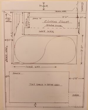
I'm not really meaning to throw a damper on things, but it looks like the space between the sliding closet doors and the layout is only ~18" in width. Wall and door thickness might make for a tight fit for a human body given that the track looks to be really close to the edge of the layout. The walkway on the right side appears to be 13", a much tighter fit.
How much of space "B" nearest the layout is actually being solidly used? Is some of that space empty so it may be combined with the walkway there to allow more room? I am also assuming that the drawing might not be truly to scale, as the 13" space in the upper right doesn't seem to be the same width as the much narrower 13" space on the bottom and the bottom-left.
While this layout can be built using the 15" radii curves in the space on the drawing, I do think that the layout overall may be problematic in several respects. Especially so if mobility is an issue as inferred in your other thread. That yard probably won't fit as drawn, one track too many, and that switch on the LH side won't fit in that loop without fudging on the 15" radius coming out the diverging route, in this case the main line. There isn't enough space for the reverse loop either. It might be time to either consider N scale or take over some of space "B".
Again I am not meaning to be a pessimist, but there are some issues here that need to be understood in advance.
Hello,
After reading your comments I thought it best to go "back to the drawing board" and check my measurements and a few other things.
It was good of you to be so detailed in your reply because it led me to discovering a few mistakes - and also deriving at some conclusions.
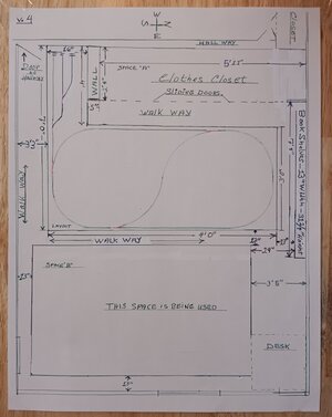
First, if you will take a look at V. #4 drawing (included here in this post) you can see all the
accurate measurements.
There is nothing more I can do than what the drawing shows with regards to the walking space on North side of the layout or the South Side -
as the room dimensions, what I have along the North side wall, and the ordered Modular Benchwork, are all "set" conditions.
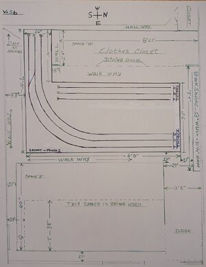
Regarding Space "B", there is a way to gain 22 inches; but unfortunately that will do me [Edited -
no good ] because of what is in the room on the North side - refer to the drawing regarding the Book Shelves down to the "Desk" - and the measurements which apply therewith. Again, this is a "set" condition.
As for your mention regarding "mobility", I must be able to reach out into the Layout from all 4 sides; and that is why I have chosen the size and shape of the Benchwork as shown. The "13" -
maybe a wee bit more - is enough for me to get into and around the layout. (There is a 3 foot, 3 inch walk space on the South side of the layout.)
BTW: The layout from the TOP to the FLOOR will be 33 inches to a max. of 36 inches - as the legs are made so there is the
ability to adjust for the
height of the layout, plus being able to make the layout
"level" through-out the entire Benchwork.
As "mobility issues" regarding getting under the layout and doing those things like wiring for example - I will have to deal with that situation when I come to it.
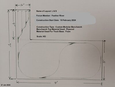
As for the "yard", I have modified the track configuration so that there will be three (3) spur tracks instead of four(4).
As for the turnout on the "LH side", again I will have to deal with it somehow.
There same goes for the "reverse loop" section of track.
Considering "N Scale" instead of HO Scale???
No, HO Scale is small enough for me! If space were not an issue, I would even opt for going to a
larger scale.
Conclusion: I may have to change my particular track scheme.
However, I will know more about that possibility after the installation of the Benchwork.

")
")