New Layout for LASM


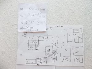
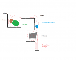
Backwards method for creating a layout. Filling the usable area with benchwork, getting a rough idea for the industries and general layout of the track, then building the tables.


layout.png


FINALLY getting going on the new layout. The lumber is ordered and I should be putting up the benchwork this weekend.

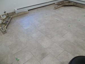
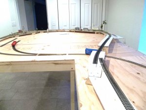
Here is a view of how I will be cutting the plywood, and some of the floor space with some old sections of track from my old layout that I will be incorporating:

astuff 001.jpg

astuff 002.jpg

The floor tiles are 12" square and this is one end. The radius on these pre built sections is 30". The table will not be attached to the wall but set out about 8" so the heat can rise from the baseboard water heaters

Thanks for looking!! lasm
 
lasm,

Good to see things coming together for your layout and that you can get a start on it. Once your bench work is done, you'll have it up and running in no time. Looking forward to the build and lots of pictures of your progress :)
 
THANKS Tony, they will be delivering the lumber today. I can spend pretty much all day Saturday putting the tables together. I will be painting the legs before I start on the terrain, and I suspect the entire project will move along in fits and starts.

That is fine.

Thanks for your interest, lasm
 
I got the plywood and boards cut over the weekend, the final dimensions are 14' x 16'.

It was suprisingly easy to get the pieces cut, using all even dimensions so the cuts on the plywood were minimized. I used simple hand tools and got everything cut in 1/2 day. The total cost for lumber plus tax was $146.00. I spend another $10 on hardware.

Next I will be screwing the pieces together and adding the legs.


newlayout 001.jpg

Thanks for looking!! lasm
 
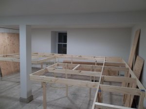
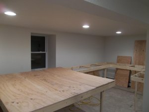
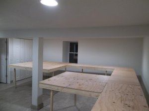
Picture of the newly completed framework with legs attached. Seriously I did not picture this by just looking at the drawing that I made, it seems larger in real life.


In this picture I just finished putting all the legs on. Some more screws will go in and an occasional brace, however, as built it has good resistance to lateral forces.

traintabl 001.jpg

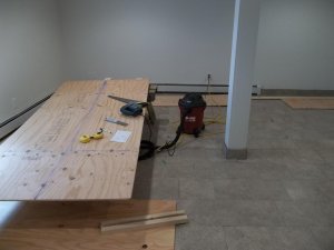
Here I threw a couple sheets of plywood on to see how it looks.

traintabl 003.jpg

The biggest challenge was adding the legs to the built framework. I did it by gradually raising it up, starting in one corner. At the end I went around with a level and adjusted the legs to get the table top level.

Cutting the plywood, building the framework, and lastly adding the legs actually worked for a free standing structure like this. Careful measurements and planning it out on paper is a requirement for success. At the end, there were 4 short pieces of 2 x 2 left over, which I can add as reinforcements as I see the need.

lasm
 
Last edited by a moderator:
Looking really good, but for a Log And Saw Man, that's what I would expect! ;)

OT a little, I was reading back through this thread and have questions about the Rix switchstand -- would it work as a ground throw, or is it only usable with a switch machine or else as a static item? Relatedly, how out of scale is the Caboose Industries high level stand that you assembled?
 
questions about the Rix switchstand -- would it work as a ground throw, or is it only usable with a switch machine or else as a static item? Relatedly, how out of scale is the Caboose Industries high level stand that you assembled?

Thanks Erik for the feedback!! The rix switchstands that I bought I think would only work with a machine, since the sliding of the points is what moves the sign. There probably is a way to use them manually if you used a stick or something to change tracks, in fact I guess it wouldn't be hard at all. I have not installed the high level stands yet but they appear to be close to scale.

I will be putting the high level stands in soon as that is the part of the track I will be starting with, I am going to have a couple manual switches on the sidings to the logging and gravel spurs.

lasm
 
The whole thing will be plywood, it is allready cut and leaning up against the wall.

I have three sections (sweeping curves with streetlights and my flashing crossing) from my old layout that I will put over the new plywood, those pieces are only 1/4" thick mahogany, and there is wiring under them so they will be 1/2" off the new plywood. There will be some foam hills, terrain put in and I will be using lightweight joint compound to get some gentle relief.
 
Sawman,

Just to follow up on a few subjects:
1)Hump Yard-You might try and find the website for the Pacific Southern, in Rocky Hill, NJ(outside of Princeton). Last I was there, they also had an operational hump yard at one end of the layout. Having seen this one and the one in Carlstadt I previously mentioned, operate, I generally tend to agree with others, that the cars typically roll downhill at breakneck speed, and slam into the car ahead, when coupling. I've seen the Carlstadt group try to decelerate the cars using air, on at least 2 layouts now. If you have a limited number of cars, and knew all of their weights, and rolling characteristics, you might be able to control them reliably, but it could take years. Also, the bowls generally are only 4-6 tracks on the layouts I've seen, and the first switch after the hump is usually a wye, with a balanced ladder on each side.

Given your latest plan, I wonder whether you'll have enough room, for the hump and bowl, where you have it currently located. As someone else said, John Armstrong's book on track design, has a section on model hump yards, and a few comments. Don't forget, in the real world, the engines usually don't go over the hump and thru the retarders, to pull out a cut of cars. Mr. Armstrong's plan includes a 'hump cutoff track,' so the yard or hump engine doesn't have to pull the newly humped string, back over the hump in reverse, to move it to the departure tracks.

2)If for no reason other than scenery, you may wish to have some scenic features below grade, such as a pond, or river. This way, you can have a scene which includes a bridge or two. You may also want to trace the old sections of layout you plan on using on your new layout, and cut these areas out, using something like a jig or sabre saw. You could them shim them to the right height. FWIW, I built a 24' x 18' layout several years back, mainly relying on a sabre saw, and variable speed drill. This time around, I've added a circular saw to my tools, to move things along faster.

3)I've learned from experience that trimming a 45 degree section of the table corner, with the two legs of the triangle being say 4", will add just a bit of aisle width, which will be helpful when you have others over. You also reduce 'pinch points,' or corners which you can get caught on, when you're in a hurry. You loose some space for scenery, but will make it easier to get around the layout. If you plan it right, you could use these triangles to fill in the interior of 90 degree turns in the table, where a curve might get very close to the inside corner of the layout.

Hope this helps!

Otis
 
The plywood is all screwed down and the slow going stuff is ahead.

atable 001.jpg


Thanks, guys, for all the comments and looking at my stuff. Tony, I admit that sometimes I envy my own train room.

lasm
 
Thanks for the comments!! I will be posting a photo tomorrow and also do a short progress video utilizing some of the imput about grades.

Thanks again, lasm
 
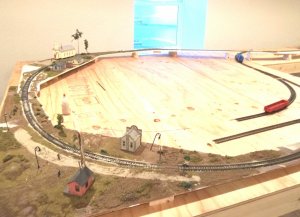
I am starting to put some track down and have some of the grade work done. The layout is still really rough but beginning to take shape:


I salvaged three of the 32" radius curves off the old suspended layout. These are getting incorporated into the new layout. I have the grades done on this end. There will be a lot more buildings added and the entire area will be filled in with landscaping, the big open area a forest with a horse logging area, loading of flat cars with logs, and a gravel extraction area:

bear2 003.jpg

bear2 004.jpg

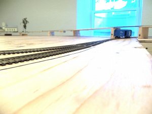
There will probably be a tunnel portal of some sort and the bottom track will disappear, the top track hugging the side of a steep hill:

bear2 005.jpg

More later, thanks for looking--lasm


Back
Top