Feedback on the wiring setup for my micro-layout


GuilfordRailman

Well-Known Member
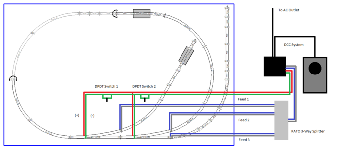
I posted this on the thread I started about my micro layout but I figured posting it here would allow others to chime in who haven’t been following the build. Wiring and electrical work is my weakness and therefore I could use feedback on if I’ve designed the wiring setup correctly. I am using Kato Unitrack and would like the layout to be DCC while incorporating a DPDT toggle switch for each turnout. The diagram below is what I’ve come up with.
KATOlayout20x33wiring.png
 
Yeah, pretty simple. Looks like ya got it right in the drawing. It's the actual connecting the wires that can get ya a short. Do one connection at a time and test the train.
 
Yeah, pretty simple. Looks like ya got it right in the drawing. It's the actual connecting the wires that can get ya a short. Do one connection at a time and test the train.
There is one part of my diagram that I’m not sure about still and that is the power going to the toggle switches. Currently it shows the power going into the dcc system. I plan on using an MRC Prodigy DCC system and there are four places where wires feed into the system, 2 for main track and 2 for programming track. If I’m not mistaken, I can’t use either of those areas for powering the toggle switches, correct? So what would be the best way to power the toggle switches?
 
I'm not familiar with the Prodogy system.
You referenced toggle switches. Do you mean turnouts on the track?
 
Here is an image I think might help demonstrate what I’m trying to achieve. This diagram shows that power for the toggle comes from a DC source. Since I plan on using a DCC system, do I have to provide a separate DC source or can I utilize the DCC system somehow to provide power?

3AFDD0D0-9181-4ACA-860E-03F854FF0B3C.png
 
I just researched for a minute and you will probably need a dc power supply. You can probably get by with a cheap 12v wall wart and will need momentary toggles.

Check this link for more info
 
I just researched for a minute and you will probably need a dc power supply. You can probably get by with a cheap 12v wall wart and will need momentary toggles.

Check this link for more info
Whoa! Right as I asked about a separate DC power supply, you posted an answer. Thanks, I’ll check it out.
 
I didn't know if the Kato's were dc or ac and that link popped up. I ran quite a few tortoise machines on an old 12v wall wart out of the junk drawer with no problems. If you don't have one laying around, Amazon has all shapes and sizes.
 
What is in the turnouts, solenoid which requires momentary contact switch or stall motor which requests constant power?
 
I didn't know if the Kato's were dc or ac and that link popped up. I ran quite a few tortoise machines on an old 12v wall wart out of the junk drawer with no problems. If you don't have one laying around, Amazon has all shapes and sizes.
Katos are DC so the 12v should work just fine. I was hoping to find a way to wire it all in the same circuit but this way should work great just the same.
 
I have modified the wiring diagram based off the feedback provided and I think a 12v wall adapter (laptop charger?) will do the trick to power the DPDT toggles.

KATOlayout20x33wiringversion2.png
 
If the turnouts aren't popping hard enough to throw the turnout all the way, you might need a heftier wall wart.
The 12V is sufficient but it might need more MAs if the power is weak.
 
If the turnouts aren't popping hard enough to throw the turnout all the way, you might need a heftier wall wart.
The 12V is sufficient but it might need more MAs if the power is weak.
Do you think something like this would be sufficient? I did read online that Kato #6 turnouts are rated for a max 12V and 3 amps. Also, the DPDT toggles I'm using are rated for a max 3 amps as well.

 
Last edited:
Most wall warts are rated in the less than 1 amp range. Yeah, 3 amps would pretty well provide ya a scale size field fire at the turnout if ya held the activation button down.
Your wall wart will have the rating on it somewhere. In that it will state voltage. ac or dc and miliamps.
 
Most wall warts are rated in the less than 1 amp range. Yeah, 3 amps would pretty well provide ya a scale size field fire at the turnout if ya held the activation button down.
Your wall wart will have the rating on it somewhere. In that it will state voltage. ac or dc and miliamps.
I'm using momentary (on-off-on) DPDT toggles so even with these should I get one with lower amps?
 
No, you won't have a problem with it unless you keep power going to the solenoid for a lot more than the momentary push of the button. Basically, the solenoid coil is sorta like a toaster if you keep power going to it. The coils will heat up like inside a toaster and eventually things start to melt or catch fire.
 
No, you won't have a problem with it unless you keep power going to the solenoid for a lot more than the momentary push of the button. Basically, the solenoid coil is sorta like a toaster if you keep power going to it. The coils will heat up like inside a toaster and eventually things start to melt or catch fire.
Ahh okay, makes sense. Perhaps a 2 amp adapter would be best then just to be on the safe side.


Back
Top