I am currently making a clock that is tied to a Z scale railroad.
I hope my explanation is clear:
I will be using a Raspberry Pi to run the railroad once per hour on the hour.
Normally, the schematic for running a motor (and that is essentially what I will be doing by supplying power to the rails), calls for some type of isoloation with a either a transistor or opto-isolator to actually switch the motor circuit on and off. I understand this, as I have built several circuits that call for this.
However, normally in this kind of circuit a clamp diode is place in parallel around the motor to keep a voltage surge from coming back through (possibly damaging the raspberry pi). In this case, the motor is the locomotive and the circuit is connected by powering the rails.
So my question is, does the locomotive engine already have a clamp diode around it, negating the use of an external one? Or if not, then exactly where would I want to put the clamp diode?
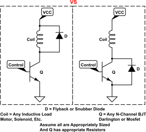
I have attached an image of a clamp diode in an operational circuit if that helps.
The VCC and ground would be the 12V supplied to ground. and the Control to the Base of the trasistor would come from the raspberry pi.
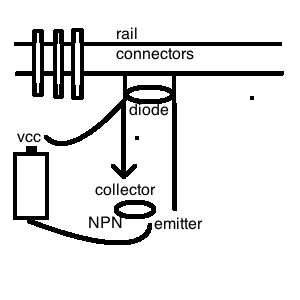
My thinking would be to put the clamp diode between both input/ground of the power to the rails. But I am not sure. Any thoughts?

jdawgaz
I hope my explanation is clear:
I will be using a Raspberry Pi to run the railroad once per hour on the hour.
Normally, the schematic for running a motor (and that is essentially what I will be doing by supplying power to the rails), calls for some type of isoloation with a either a transistor or opto-isolator to actually switch the motor circuit on and off. I understand this, as I have built several circuits that call for this.
However, normally in this kind of circuit a clamp diode is place in parallel around the motor to keep a voltage surge from coming back through (possibly damaging the raspberry pi). In this case, the motor is the locomotive and the circuit is connected by powering the rails.
So my question is, does the locomotive engine already have a clamp diode around it, negating the use of an external one? Or if not, then exactly where would I want to put the clamp diode?
I have attached an image of a clamp diode in an operational circuit if that helps.
The VCC and ground would be the 12V supplied to ground. and the Control to the Base of the trasistor would come from the raspberry pi.
My thinking would be to put the clamp diode between both input/ground of the power to the rails. But I am not sure. Any thoughts?

jdawgaz


