clamp diode needed in wiring?

ModelRailroadForums.com is a free Model Railroad Discussion Forum and photo gallery. We cover all scales and sizes of model railroads. Whether you're a master model railroader or just getting started, you'll find something of interest here.


jdawgaz

New Member
I am currently making a clock that is tied to a Z scale railroad.

I hope my explanation is clear:

I will be using a Raspberry Pi to run the railroad once per hour on the hour.

Normally, the schematic for running a motor (and that is essentially what I will be doing by supplying power to the rails), calls for some type of isoloation with a either a transistor or opto-isolator to actually switch the motor circuit on and off. I understand this, as I have built several circuits that call for this.

However, normally in this kind of circuit a clamp diode is place in parallel around the motor to keep a voltage surge from coming back through (possibly damaging the raspberry pi). In this case, the motor is the locomotive and the circuit is connected by powering the rails.

So my question is, does the locomotive engine already have a clamp diode around it, negating the use of an external one? Or if not, then exactly where would I want to put the clamp diode?

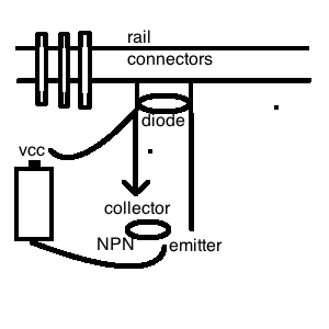
I have attached an image of a clamp diode in an operational circuit if that helps.
The VCC and ground would be the 12V supplied to ground. and the Control to the Base of the trasistor would come from the raspberry pi.

My thinking would be to put the clamp diode between both input/ground of the power to the rails. But I am not sure. Any thoughts?

flybackdiode.png

jdawgaz
 

gregc

Apprentice Modeler
inductors, such as motors, want to maintain current flow. The voltage across the inductor is proportional to the change in current. (yes, the voltage is zero when the current is constant, regardless if it is 1 ma or 100 A).

in the circuit on the left, the diode allows current to flow back around through the inductor when the transistor shuts off abruptly. This minimizes the voltage induced across the inductor due to the change in current.

in the circuit on the right, the diode does not provide a path for the current when the transistor is not conducting.

i believe your circuit will connect Vcc and the transistor (collector) to the rails. The diode can be part of your circuit, not directly on the motor and would be connected just as you've drawn it on the left side.
 

jdawgaz

New Member
inductors, such as motors, want to maintain current flow. The voltage across the inductor is proportional to the change in current. (yes, the voltage is zero when the current is constant, regardless if it is 1 ma or 100 A).

in the circuit on the left, the diode allows current to flow back around through the inductor when the transistor shuts off abruptly. This minimizes the voltage induced across the inductor due to the change in current.

in the circuit on the right, the diode does not provide a path for the current when the transistor is not conducting.

i believe your circuit will connect Vcc and the transistor (collector) to the rails. The diode can be part of your circuit, not directly on the motor and would be connected just as you've drawn it on the left side.

ok. This is what I am thinking.

Connect Vcc to left rail connector, left rail connecter to collector of transistor.
Connect Gnd to emitter of transister, and from there to right rail connector.
Connect Diode between left rail connector and right rail connector.

sort of like this: (I am not a good drawer)
 

Attachments

  • railroad.png
    railroad.png
    11 KB · Views: 262

gregc

Apprentice Modeler
Connect Vcc to left rail connector, left rail connecter to collector of transistor.
Connect Gnd to emitter of transister, and from there to right rail connector.
Connect Diode between left rail connector and right rail connector.

not sure I understand.

connect Vcc to one rail and the collector to the other.
connect the diode across the rails: cathode on the Vcc rail like you drew on the left side of your first figure
 

jdawgaz

New Member
it worked. I guess I got hung up in my thinking about one rail being + and the other -.
doh. thanks for getting my head "out of that mode".


Affiliate Disclosure: We may receive a commision from some of the links and ads shown on this website (Learn More Here)


ModelRailroadForums.com is a participant in the Amazon Services LLC Associates Program, an affiliate advertising program designed to provide a means for sites to earn advertising fees by advertising and linking to amazon.com

RailroadBookstore.com - An online railroad bookstore featuring a curated selection of new and used railroad books. Railroad pictorials, railroad history, steam locomotives, passenger trains, modern railroading. Hundreds of titles available, most at discount prices! We also have a video and children's book section.

ModelRailroadBookstore.com - An online model railroad bookstore featuring a curated selection of new and used books. Layout design, track plans, scenery and structure building, wiring, DCC, Tinplate, Toy Trains, Price Guides and more.

Top