'1943, Somewhere in England', N scale Monster Layout


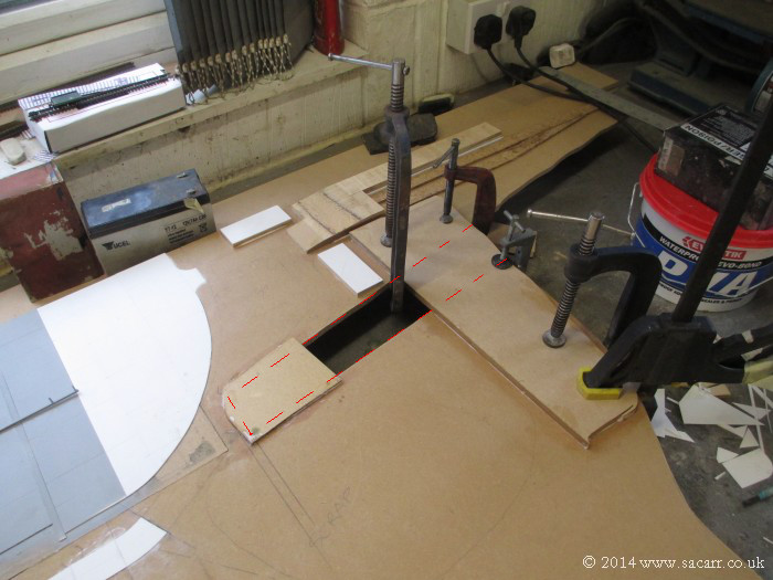
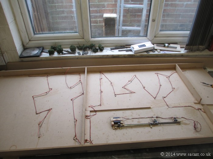
The Catalina mechanism cost me £0.00 in materials, all salvaged bits. I don't need to control the speed, a micro switch stops it. It is simple, it is cheap, it cost nothing in parts or shipping. Why add electronics for the sake of it when it's not necessary? If the layout was for myself, it wouldn't be DCC and would probably have manual points control. Unnecessary electronics just adds cost and manufacturing time.

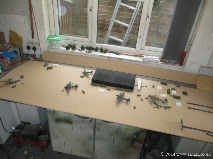
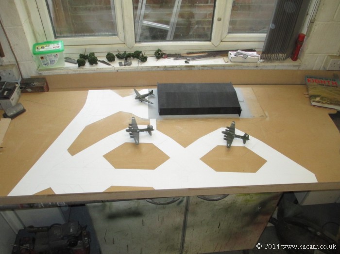
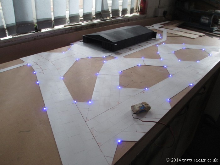
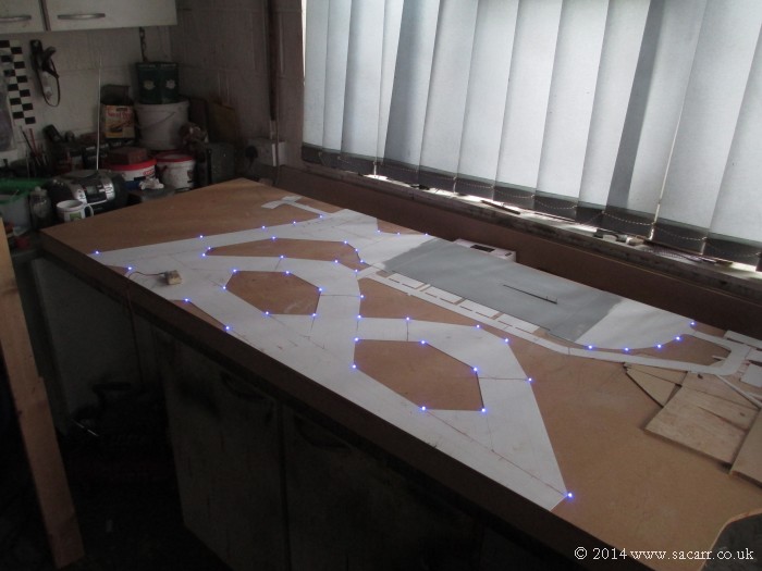
This is a project for a customer, not a personal toy for myself. As a result, it is built to a budget in both time and materials.
 
A shopping trip this morning resulted in a large 8ft x 30inch sheet of MDF filling my workbench. Most of the rest of the day was spent plotting and marking out where everything goes on this section. Here's an overview with the completed items in place.

airfield107.jpg


To the left of the perimeter track is the airfield itself, where an RAF Lancaster has made a forced landing. Its landing gear has collapsed, dragging it off the runway, and onto the grass near the perimeter track.

airfield108.jpg
 
The Control Tower, fire truck shed and blast shelter. The tower was made for another project some time ago, and then never got used. It has finally found a home.

airfield109.jpg


Looking to the right of the tower, over the perimeter track, is the T2 hangar. The C-47 Skytrain is parked outside this end of the hangar. In front of the hangar are two loop dispersals with the B-17 Fortresses parked on them, being prepared for the next mission.

airfield110.jpg
 
The other end of the hangar shows the Catalina being towed out, and near by, the "Hangar Queens"; damaged airframes slowly being stripped of useable parts.

airfield111.jpg


Here's the hangar queens and other wrecked airframe parts. I think I still need to add a few more bits and pieces here. Near by, more of the technical site buildings and blast shelters.

airfield112.jpg
 
To the right of the technical site are the two sidings for supplying goods to the airfield. A raised platform will be behind the rear track for unloading of goods from wagons and flatcars, while the nearside track has the pump house to unload fuel tankers to the underground fuel stores.

The track going into the tunnel is the climbing track from the main line leading up to the airfield and mine branchline.
airfield113.jpg


Moving forwards on the layout, the three mainline tracks from the station, merge into two lines which vanish into tunnels below the airfield. These three lines through the station allow a passenger train to be stopped at either platform, while allowing goods trains to continue on their journey.

airfield114.jpg
 
At the front of the layout, is the branchline that leads to the quayside.

airfield115.jpg


After everything had been marked out, the whole board was painted with dilute PVA, as this makes it easier to use cyano glue to attach the perimeter tracks and dispersals. Once dry, the last job of the day was to cut the board where the hangar floor and its mechanism goes, and to start gluing a small stiffener to the airfield board. This upstand will give clearance to the hangar mechanism and other wiring on the bottom of this piece while I am working on it.

airfield116.jpg
 
The first part of the morning was spent gluing further stiffening strips to the bottom of the baseboard. The hole for the hangar base had some strips glued around the edge to support the hangar base piece, and once they were dry, the hangar section was fitted.

airfield117.jpg


Time for the perimeter track. Styrene strips were cut to suit the standard 50 feet wide track. The concrete slabs were scribed into the top surface and the bottom was roughed up with 80 grit sandpaper to key it for gluing.

airfield118.jpg
 
The track end of the board was cut away and the cork bed was added to the airfield sidings.

airfield119.jpg


The first two sections of the perimeter track and dispersals added.

airfield120.jpg
 
By the end of the day, most of the dispersal was laid and scribed. Tomorrow the rest of the peri-track and dispersal should be done, and the roads and pathways added. A bag of LED's and wire turned up today so the airfield lighting can begin soon.

airfield121.jpg


airfield122.jpg
 
The first job today was to finish the aircraft dispersals.

airfield123.jpg


While those bits were weighted down, I started on the curved area of the peri-track. I decided it was least wasteful by making it in individual concrete slabs, rather than cutting a curved section.

airfield124.jpg
 
In the centre of each dispersal area, is a ring of tie down points. These were metal loops concreted into the ground. To represent these, I've drilled holes to represent the depressions in the concrete around each ring.

airfield125.jpg


airfield126.jpg
 
At this point, I took advantage of the mild weather for a couple of hours, and refitted the fender on the Jeep, took it outside for an engine run and to get some photographs for the insurer with the registration on.

0741.jpg


Once the Jeep was done and back in the garage, I went back to spend another hour to finish the day on the railway. The concrete area in front of the hangar was completed, along with the concrete joining it to the perimeter track.

airfield129.jpg


It's quite time consuming cutting the parts, scribing them with the join lines and gluing them down, but it does look good, and will be better once painted and weathered.

airfield130.jpg
 
April 7th - Here's the road to the Control Tower, fire truck shed and blast shelter.

airfield131.jpg


At the other end of the board, the beginnings of the loading platform were made. To the left, a piece of MDF raises the ground height in this area. This also strengthened the board in this area where a cut out had been made.

airfield132.jpg
 
The cut out, shown below, is to give more clearance for the track leading up from main line height up to the airfield and mine.

airfield133.jpg


This area was soon filled in with more wood to build up the surface height, allowing just a thin skim of plaster. Roads, pathways and hut bases were added with styrene.

airfield134.jpg
 
Along side the T2 hangar are four more hut bases.

airfield135.jpg


Around the perimeter tracks and dispersals, a number of holes were drilled for the airfield lighting.

airfield136.jpg
 
A number of particularly deep joins in the 'concrete' slabs were filled with fine surface filler.

airfield137.jpg


The loading platform was also completed with its top surface added.

airfield138.jpg
 
April 14th - It took some time to solder up the resistors to the LED's. The beginnings of a chest infection also slowed progress.

airfield139.jpg


The LED's were pushed into the baseboard using a small depth gauge to keep them consistent. A dilute mix of PVA glue was painted around the top of each LED where it met the board to tack them in place.

airfield140.jpg
 
Once the glue had tacked off, the board was turned over and the back of the hole was filled with glue to hole the LED's firmly in place.

airfield141.jpg


On April 16th, the insurance cover began for the new Jeep, so the morning was spent tinkering with that, checking it over and bedding in the handbrake shoes with the transmission turning. Three short drives followed in the afternoon, with no major issues; a relief for my first vehicle rebuild.

0756.jpg
 
My chest infection got worse, limiting what I've been able to do, and that together with the Easter holiday has limited the time on the project. However the airfield lighting wiring was completed. It is a little more messy than usual, going directly from LED to LED, rather than horizontally and vertically across the board. However, as there will be virtually no other wiring on the bottom of the airfield, I didn't see it worth while wasting more wire than needed.

airfield142.jpg


The hangar has also been wired to have red warning LED's on the top, but these are yet to be connected to the rest of the circuit. The perimeter LED's will have a painted top or cover added, so that their light shines sideways rather than up.

airfield143.jpg


airfield144.jpg


Back
Top