armyairforce
Well-Known Member
Since getting back into railroading in 2005, I built three N scale layouts for myself. 'Dreamland' was the first on a 6 x 2ft board. 'Area 51' was next with a similar but enlarged track plan on an 8 x 2ft 6in board, both of which operated diesels. My last layout was 'Storage Depot 41, Kingman' which was 11ft 6in x 2ft 6in in size, set in 1945/46 and was all steamers. All three railroads were designed as transportable exhibition layouts and ended up being sold soon after completion after someone showed an interest. As a side note, I spotted the 'Area 51' layout on Ebay the other day which is currently with its third owner.
The current N scale layout is a monster at 30 x 11ft, but it isn't for me, it's for a customer. As you can see from the title, the layout is set in England during World War Two. Like my previous layouts, it will have some military content, in addition to the more usual things you find on a UK railway. There will be plenty of opportunity for scratch building and kit bashing, and the English countryside will be a nice change from the desert/rocky US layouts I have been building. The layout will be built in sections, as it needs to get from my workshop to its final home, but this means each section can be built to completion so I'm not spending several months just on benchwork.
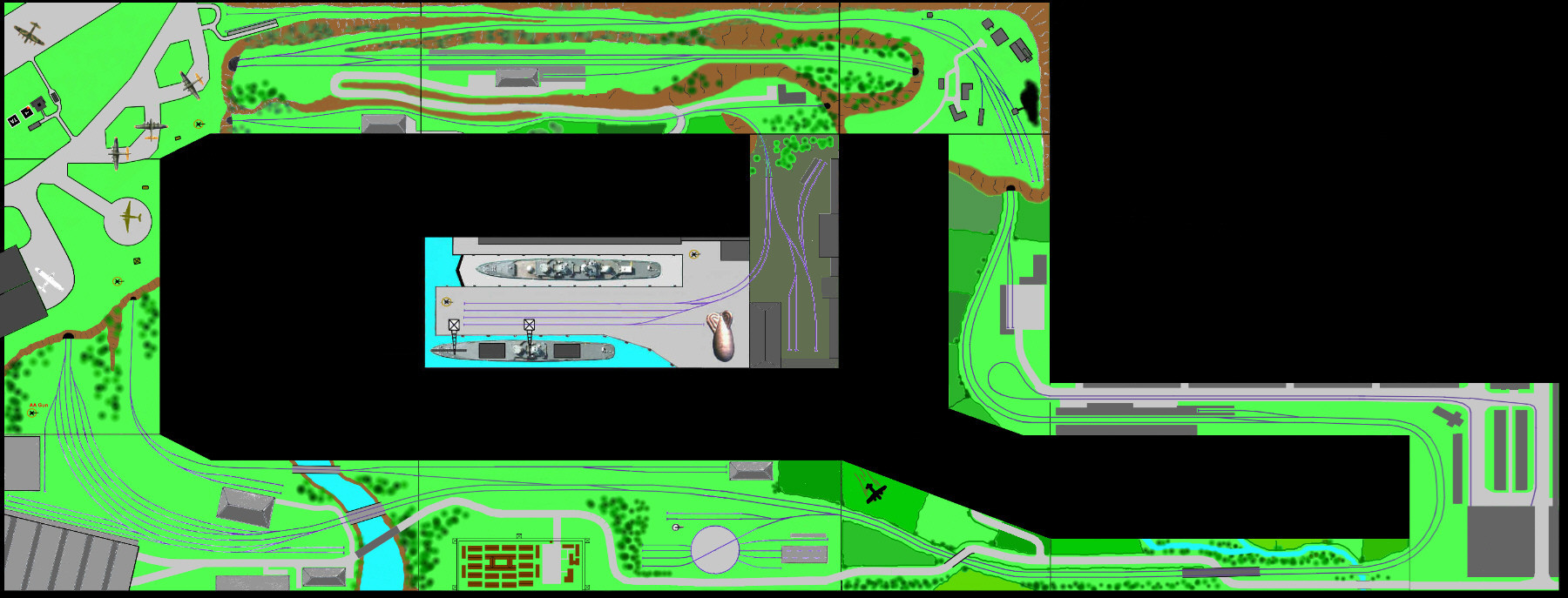
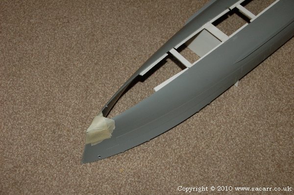
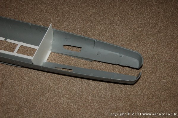
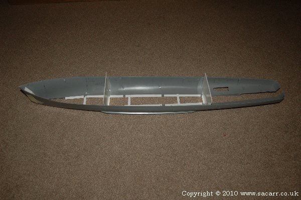
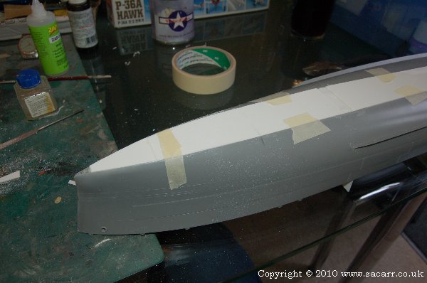
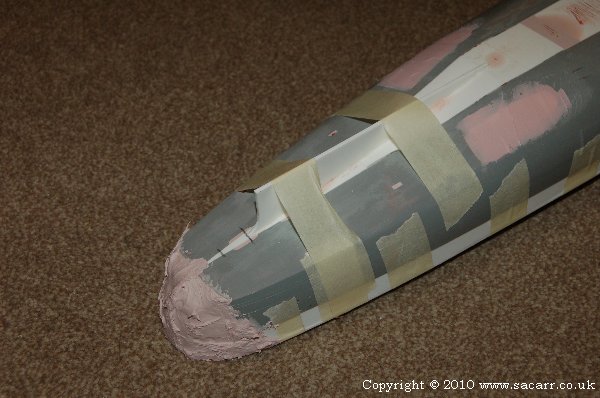
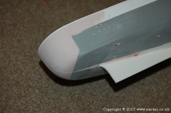
There is a quayside and goods yard in the centre. To the South West, there are Munitions factories and other industries. Proceeding East along the layout is a river, POW Camp, Loco Depot and countryside with a viaduct on the approach to the town. Near by, a Junkers Ju88 bomber has force landed, and Home Guard troops protect the wreckage from school boys looking for a souvenir.
After the viaduct, there's a large town and tramway with a large station. To the North, a loco refurbishing works ( as both locomotives and rolling stock were in short supply during the war ). North again is a Coal Mine, and to the West, a countryside station. Further West, the edge of US bomber airfield can be seen.
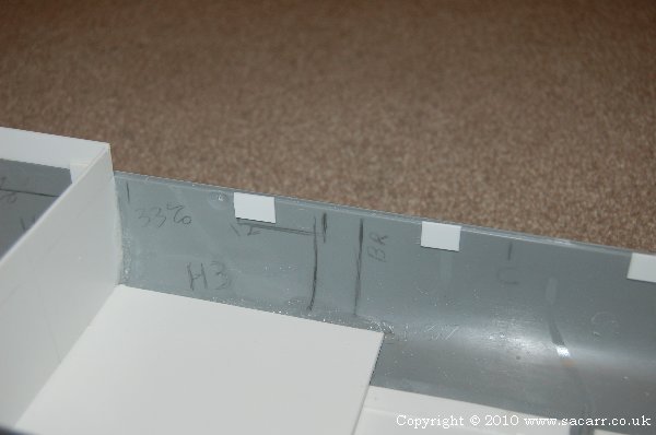
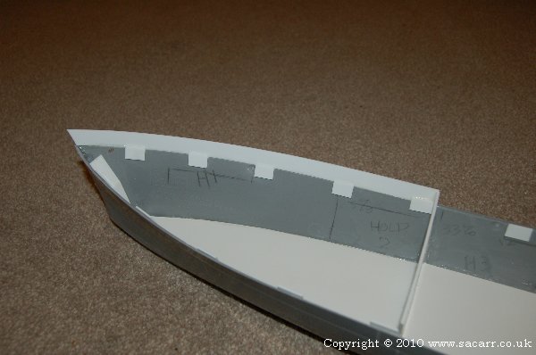
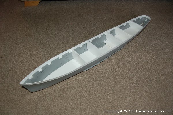
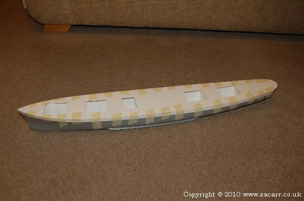
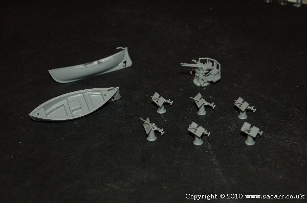
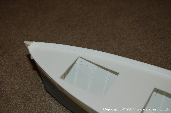
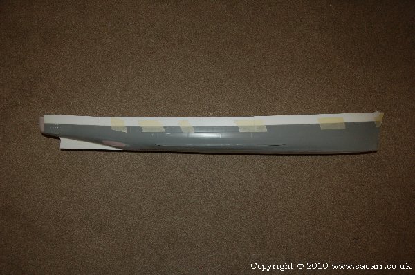
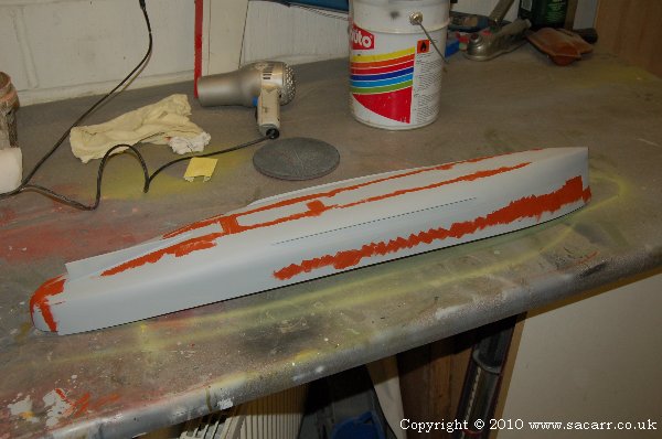
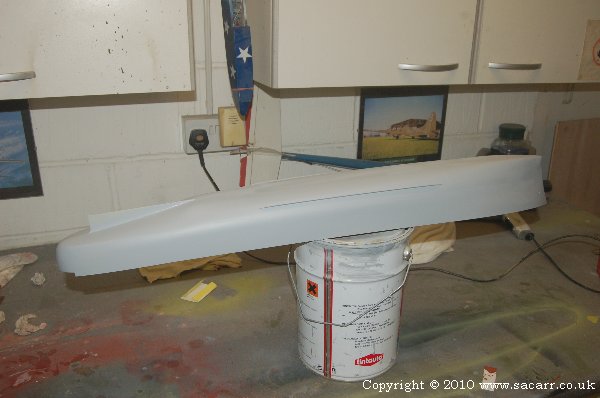
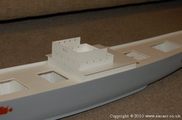
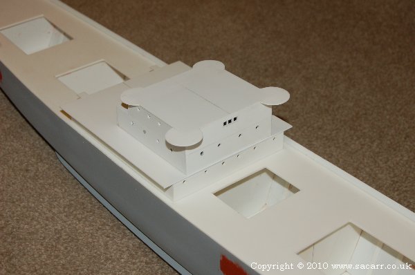
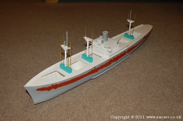
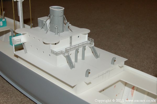
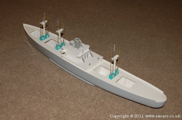
Construction began in December 2010 with one of the most detailed sections of the layout, the quayside and dry dock. At 6 x 2 feet, it was a smallish section to start on but with plenty of variety in terms of structures and detail.
As I write this, I am currently working on the third section, so the thread has got a little catching up to do before you start seeing stuff in real time, but I hope you find the work I've done since the turn of the year interesting. Here's the track plan. Basically a two track main line with a branchline down to the quayside and another leading to the mine and airfield. This gives the option for continuous running over a nice long journey, and plenty of switching opportunities assembling trains. Click on the plan image for a larger version.

The current N scale layout is a monster at 30 x 11ft, but it isn't for me, it's for a customer. As you can see from the title, the layout is set in England during World War Two. Like my previous layouts, it will have some military content, in addition to the more usual things you find on a UK railway. There will be plenty of opportunity for scratch building and kit bashing, and the English countryside will be a nice change from the desert/rocky US layouts I have been building. The layout will be built in sections, as it needs to get from my workshop to its final home, but this means each section can be built to completion so I'm not spending several months just on benchwork.
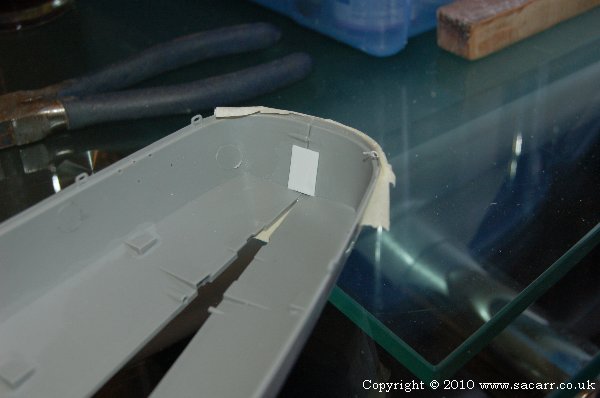
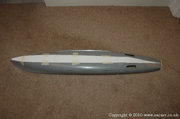
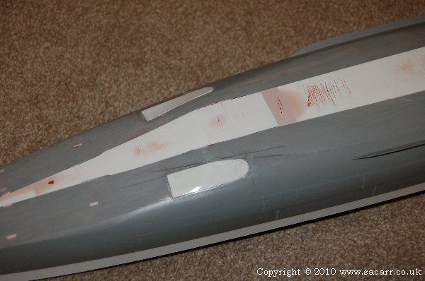
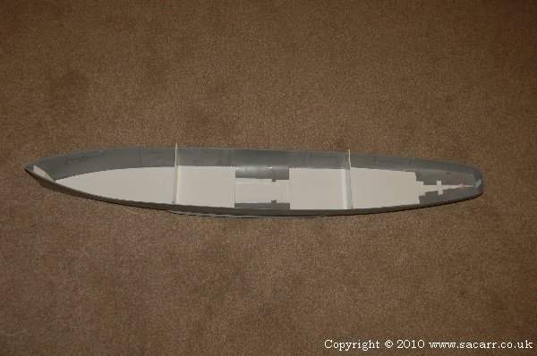
There is a quayside and goods yard in the centre. To the South West, there are Munitions factories and other industries. Proceeding East along the layout is a river, POW Camp, Loco Depot and countryside with a viaduct on the approach to the town. Near by, a Junkers Ju88 bomber has force landed, and Home Guard troops protect the wreckage from school boys looking for a souvenir.
After the viaduct, there's a large town and tramway with a large station. To the North, a loco refurbishing works ( as both locomotives and rolling stock were in short supply during the war ). North again is a Coal Mine, and to the West, a countryside station. Further West, the edge of US bomber airfield can be seen.
Construction began in December 2010 with one of the most detailed sections of the layout, the quayside and dry dock. At 6 x 2 feet, it was a smallish section to start on but with plenty of variety in terms of structures and detail.
As I write this, I am currently working on the third section, so the thread has got a little catching up to do before you start seeing stuff in real time, but I hope you find the work I've done since the turn of the year interesting. Here's the track plan. Basically a two track main line with a branchline down to the quayside and another leading to the mine and airfield. This gives the option for continuous running over a nice long journey, and plenty of switching opportunities assembling trains. Click on the plan image for a larger version.