'1943, Somewhere in England', N scale Monster Layout

ModelRailroadForums.com is a free Model Railroad Discussion Forum and photo gallery. We cover all scales and sizes of model railroads. Online since 2002, it's one of the oldest and largest model railroad forums on the web. Whether you're a master model railroader or just getting started, you'll find something of interest here.


I had another meltdown with the computer and programmer today. Nothing wrong with the programmer, but the 'Locoanalyse' program froze every time it was launched. As previously mentioned, I ended up running the program on my laptop with XP, but I was getting ahead of myself there. It did start out working on my new laptop with Windows 7. It was fine to start with on W7, but suddenly stopped working. I installed it on my old laptop running Windows XP and it worked fine. So I'm guessing my new laptop did some update that conflicts with the 'Locoanalyse' program.

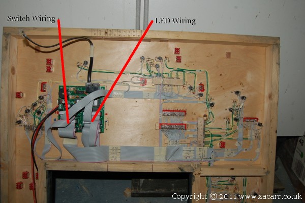
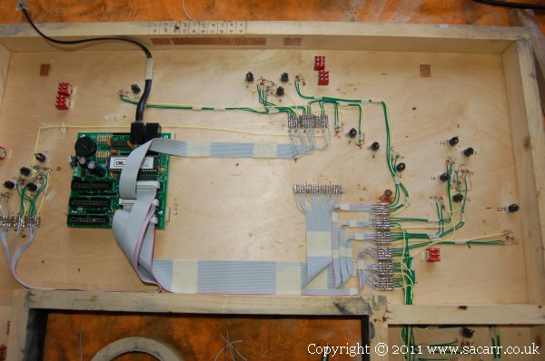
Anyway, I did more wiring today. I finished connecting up the ribbon cable to the LED's and ran the DTM30's test feature to see them all light one by one. Only two didn't light. One hadn't quite touched the return wire during soldering, while the other had a slight fracture in the PCB between the ribbon cable and the wire to the LED. All worked after a quick resolder.
quay_yard232.jpg


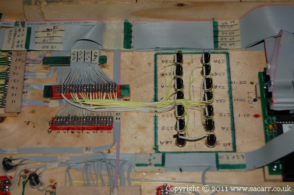
The next lot of wiring is the ribbon cable that connects up the push buttons that operate the points and other features. At the end of the day, I was part way through the switch wiring.
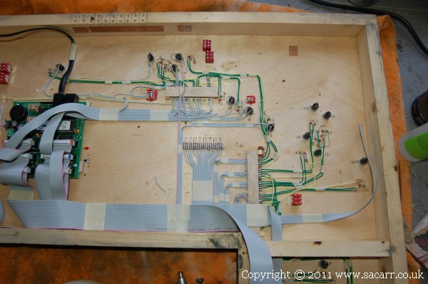
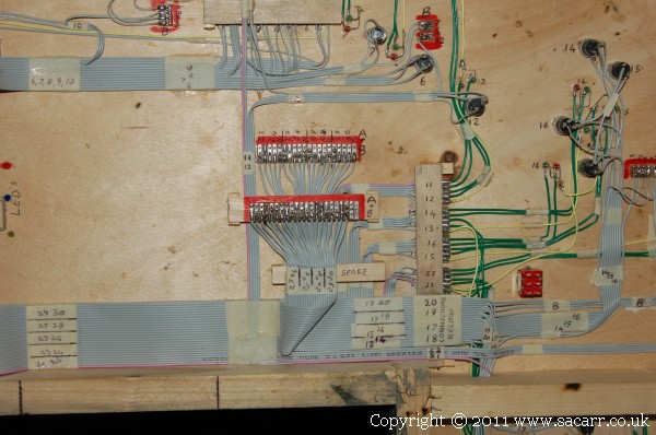
quay_yard233.jpg
 
All the LED's and push buttons are now connected. At last!

quay_yard235.jpg


All the terminals surrounded by a red border are spare input or output wires. Some of these will be wired up to the DTM's 'Programmed Route Facility' and 'Emergency Stop' buttons.

quay_yard236.jpg
 
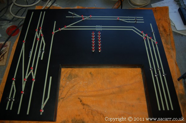
Here's the back of the panel showing the 14 switches mounted next to the DTM30. These will be for the programmed routes.

quay_yard239.jpg


and the front view.

quay_yard240.jpg


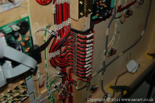
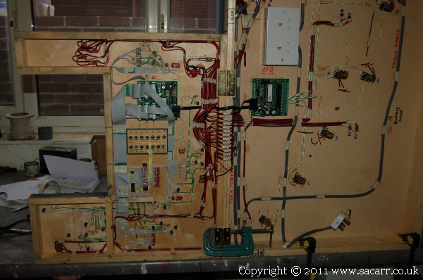
With all the wiring in the panel done, the next stage was to connect the panel to the layout. All of these wires are power lines to the various isolated sections in the two yards.

quay_yard246.jpg


A general view of the panel connected. There's a lot of wires in there, but by keeping them pretty much straight runs, it's as tidy and neat as it can be.

quay_yard247.jpg
 
August 10th - I had an afternoon of frustration and excitement in equal measure. I struggled to get the DAC20 to respond to the programming. It seemed completely dead. I was powering it via an aux supply rather than track power. Not getting anywhere, I tried the aux power in the track power input, and it came to life. Hmmmm? Back in the Aux input, and nothing. Out came the instrucitons AGAIN, and reading through once more, I found a small section which says the aux input only powers the CDU's and output side of the board, not the main circuit. So, after wiring a second power supply into the track input, it came to life and would accept programming.

I got the DTM30 and DAC20 programmed with the same values to allow the control panel to work the points using matching decoder addresses. On the DTM30, each button can be assigned an individual address, but I found out today that on the DAC20, you set the first address in the sequence, it it automatically assigns addresses in sequence from this number. This meant that the previously programmed DTM30 had to be modified from the original sequence of points I originally set up. This involved numbering each point on the layout plan to match them to the local DAC20 rather than points by yard, station, branchline etc.

So all the points would be numbered from 1901 upwards. This would keep all the point addresses clear of lower numbers which I plan to use for loco addresses ( matching the loco's cab number to an address to make it easy to identify them ). So the DTM and DAC were programmed, the final point solenoid connections made to the DAC20 and it was all powered up. After further confusion with the DTM30 settings to operate it correctly, it all came to life and points changed when I pressed buttons!!! Woo Hoo!!!!!

Then it all went pear shaped again when I got the Digitrax DS64 point decoder that would operate the quayside. The instructions say it can have addresses from 0 to I think 2024. No problem, I needed addresses 1901 to 1904. Then I hit a brick wall. The computer program is designed for the CML Electronics devices, but the Digitrax DS64 has to be programmed via the throttle. On selecting the menu for selecting points, it seems that it can only use addresses from 0-999, where as loco addresses can be from 0-9999. SO,.. the DTM and DAC's had to be reprogrammed with new addresses to follow on from the DS64 numbers.

With that finally worked out and tested off the layout, the phone rang. It was Lynne wanting me to pick my daughter up from nursery, so that was the end of the work for the day. So a day with much frustration, but I finally feel like I'm getting somewhere and finally wrapped my head around the operating system. Now that I know near enough what I'm doing, the rest of the layout electronics should go much faster.
 
The following day was another busy one, with my head burried either in my keyboard, the programming software or the back of the control panel. I worked out routes, and did several test routes. I also discovered that the DAC20 outputs can only operate one point.

I'd read somewhere that an output could operate two points, ie for a crossover, and so wired the panel accordingly. It turns out it was the Digitrax DS64 that can power two at the same time. The DAC can't, so I'm in the middle of rewiring the panel buttons for the crossover by the station to allow two separate functions. This meant I needed another point address available, so the plan for the decoders on the whole layout needed to be adjusted slightly. So the original plan was labelled with all the point decoder numbers, and a decoder position marked with eight arrows to the points.

This should make future connections and programming easier to follow. I've now set up routes through each station platform and using the passing track between the platforms. Further routes need to be set up to send trains through to the quayside from the branchline approach. I finally feel like I'm controlling the circuits rather than them controlling me! It's been a steep learning curve, but hopefully now I can pass on the 'how to' to Rob so his life will be easy in the future.
 
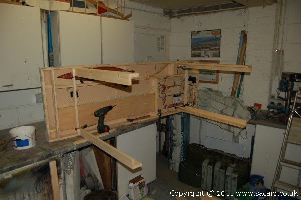
With the assembly and testing of the first two sections getting close, I decided I did need some legs making for the sections. Originally, I wasn't going to make any until late in the project, so I didn't have to store them, but testing is going to be easier with the layout on legs rather than my building bench. Both the quayside and quayside yard are lower than the rest of the layout, so the legs need to be cut shorter, but that will have to wait until section three is made to match up the height correctly.

The quayside section has the legs glued on for now. Two of the power supplies for that section stick out below the board, so after testing, the legs will be cut off, leaving short stumps which will support the section with the power supplies clear of the ground. Once the legs are cut to the correct length, they will be bolted back to the stumps.

quay239.jpg


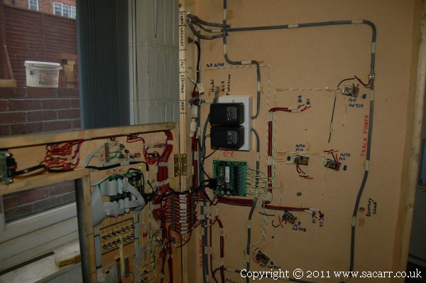
The DS64 point decoder has also been refitted and the points connected up now that it has been programmed.
 
Here's the bottom of the yard section again. I've spent so much of this week staring blankly at the circuits, programmer and laptop!!! The two black power supplies feed the DTM30 control panel circuit and the output of the DAC20 point decoder.

quay_yard249.jpg


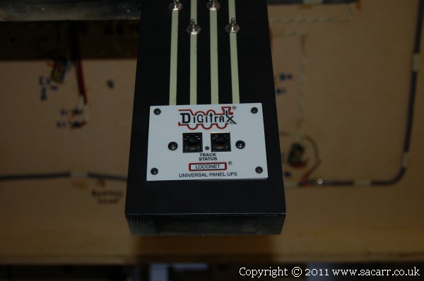
The UP5 interface for the throttle has been mounted to the end of the control panel. Infra-red interfaces with be spread around the layout, but since this came with the Digitrax command station, I decided to use it at a location where not much wandering was required. It looks slightly wonky on the panel, but is in face square, however the label on the front of the unit isn't quite square to the aluminium mount. I didn't want to try and peel it off in case it ripped. It was obviously a Friday afternoon in the factory when that one was assembled!

quay_yard250.jpg
 
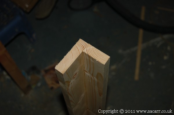
The legs were made from pieces of 70mm x 18mm and 44mm x 18mm glued and screwed together in an 'L' section.

quay_yard251.jpg


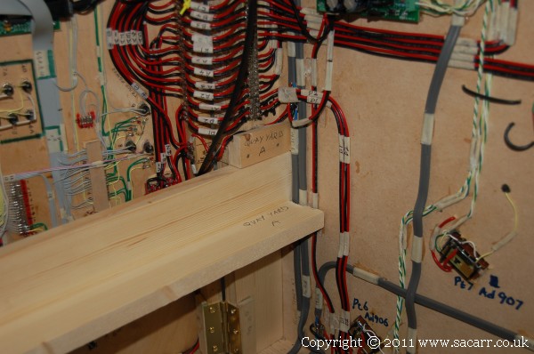
The legs for the yard won't be glued for now. They will be bolted in place, but to reinforce the joint to prevent the bolts taking all the load, some blocks of wood were glued into the frame either side of the leg position.

quay_yard253.jpg
 
August 17th - I'd been full of cold for several days, but forced myself to go out to the workshop. I got the legs bolted to the yard using M8 bolts with 'T' nuts set into the legs. I then struggled a bit, carefully lifting the section down off the bench onto the floor. After a bit of shuffling the sections around the workshop floor to get them to fit together and leaving space to get around them, they were bolted to each other.

One rail didn't quite meet as well as I would have liked, so it was resoldered in a better position and rolling stock pushed over the joints to check everything. Track power and isolation wiring was then connected between the two boards, plus the fifth point control wires on the quayside section, as the Digitrax point decoder on that section only has four outputs. All the track was then cleaned with a track rubber and then vacuumed clean.


The track was then connected to a DC controller set at about 5 volts, and continuity and polarity were checked along each track and point. Once that was done. A DC loco was test run around all the tracks. It got stuck at a few places and on the points. The points still had traces of paint between the blades, and after scraping clean, were ok. The other spots were areas where the styrene 'concrete' was a little high, lifting the wheels clear of the rail, so loosing electrical contact. These areas were scraped with a blade to lower the height, and will have to be touched in with grey later.

With that done, the Digitrax unit was connected up and switched on. I got power through the Loconet wiring, as the throttle was live and the DS64 point decoder worked the quayside. While the control panel LED's were glowing, none of the other points were moving and there was no track power! I quickly realised that the points wouldn't work as the DAC20 uses track power for its circuit, and with no track power, it was dead. Nothing I did could restore track power, including unplugging the Digitrax Command station from everything but the interface and throttle, but still no track power.

It was all disconnected and wired up to the test loop of track I made ages ago. Just before I turned the mains power on, the little light came on in my head! I hadn't turned the power switch to ON on the throttle! So it was all unplugged again, wired back up to the layout and powered up, including the throttle power switch. It all came to life!
 
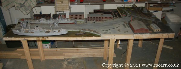
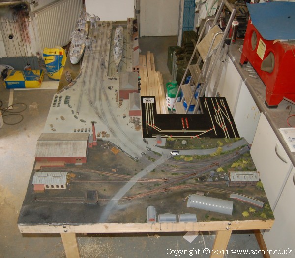
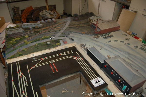
OK, here's the pictures. Both sections on their legs and bolted together. These sections measure 8 feet x 4 feet over all. For many people, that's as big as their layout gets.

quay_yard254.jpg


Two views, the first from the town section position, the second from the quayside operators position. At the road intersection, a bus can be seen. This was an addition along with some more figures; more people heading for the factory.

quay_yard257.jpg
quay_yard259.jpg
 
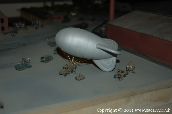
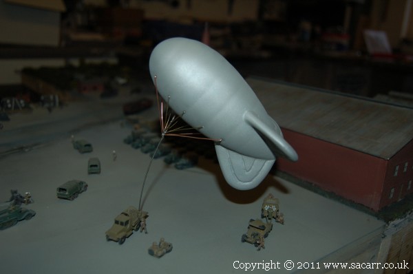
I think I burned myself out doing the wiring and test run and still being unwell, so I had a couple of days break. Once back to it, I made the rigging for the Barrage Balloon. This was made from soldered brass wire for the rigging cables, and thin piano wire for the main winch cable.

balloon26.jpg


I wanted the balloon to be floating above the winch truck, but not far. The weight of the balloon though is still a bit heavy for the piano wire as can be seen below. I don't want to use a thicker wire, so I think I'll add another wire cable at the rear of the balloon with a soldier on the ground 'holding it'. This will help support the rear of the balloon while looking like a rope to control it's direction.

balloon27.jpg
 
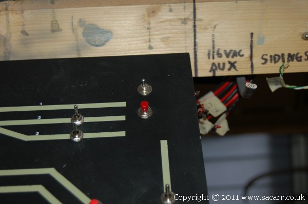
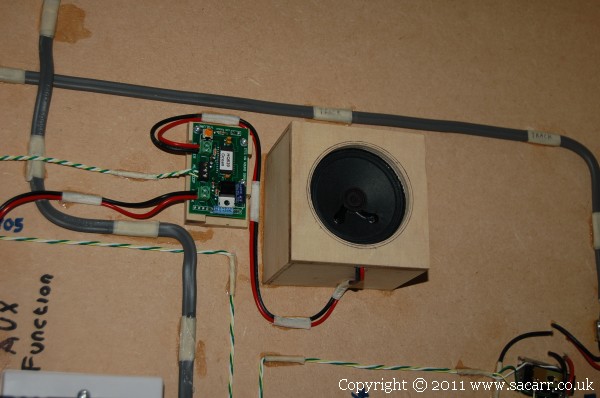
August 23rd - I fitted the sound chip and speaker that provide the coastal sounds such as seagulls, fog horn etc. The 2.5in speaker was mounted in a ply box to act as a sound box and two switches mounted on one of the few spare areas of the control panel. The push button runs the sequence once while the toggle switch allows for looped continuous sound.

Video of the sound chip here - http://www.youtube.com/watch?v=UpTKey464aw

quay_yard263.jpg
quay_yard264.jpg


I also added some more wires to the Barrage Balloon, but after a trial fit, I decided this would be better fitted once the layout is installed. While it could be mounted now, it's still got to survive a road trip to its final home, and there's too much potential for it to break free or bend the supporting wires.
 
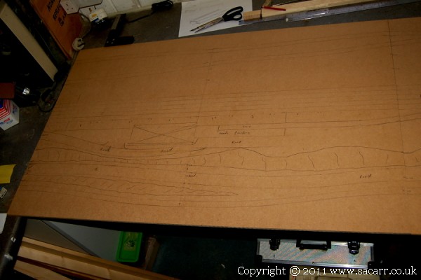
Later in the day, I took a trip out to B&Q and came back with some more strip timber and a cut down 8x4 MDF sheet. I then spent the rest of the afternoon marking out the track, road and hill positions on the MDF, prior to it being cut to allow the three different track levels to be made.

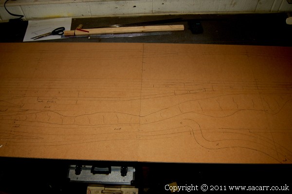
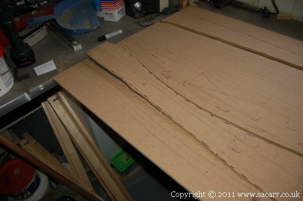
Here's some pictures of the Countryside Station section, mostly marked out. The contrast has been boosted to help show the pencil lines. This section is 8 feet long by 2 feet 6 inches wide. This was the complete size of my Area 51 Layout built a few years ago. It will be split into three levels.

cstation1.jpg


The Branchline leading to the quayside will start at quayside yard height at the right hand end, and slowly rise to the left at a grade of around 1 in 50. It will slowly gain height over half the layout until it finally meets the mainline. At the right end of the branch, there will be a Clay Works on the line leading into a single track tunnel. This tunnel will be the location of the "Kelly's Heroes" tribute, with three Shermans exiting the tunnel.

cstation2.jpg
 
Last edited:
The Mainline on this section will be five inches above the lowest branchline position. The road from the quayside crosses the branchline and gains height to the left, up the hillside, doubling back on the next section, reaching the mainline height at the station. The station has two platforms for passengers which will probably handle a train of five coaches. There is also a small siding for the unloading of goods and cattle. A water tower will be located here.

Two inches above the mainline height is the branchline to the mine and airfield. The track linking the branch to the mainline decends from this section, linking up to the outer mainline on the airfield section.

cstation3.jpg
 
August 25th - Today I went into the workshop to work on the layout, but it was one of those days where everything got dropped, fell over, went missing etc. You get the picture. I should have stayed in bed! I persisted however, and made reasonable progress on the Country Station section woodwork.

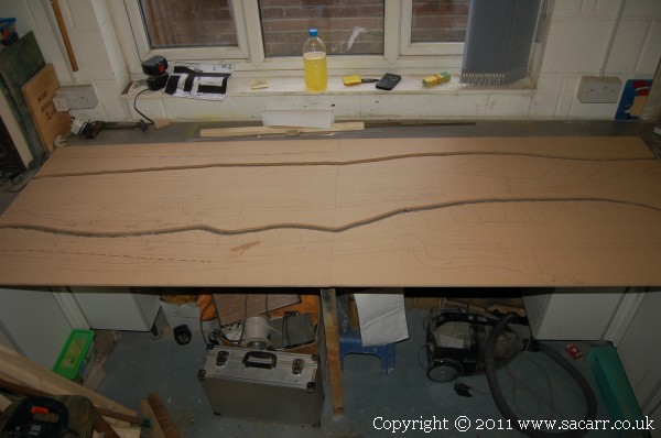
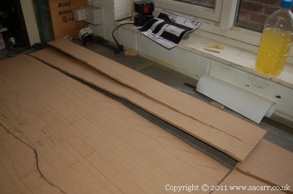
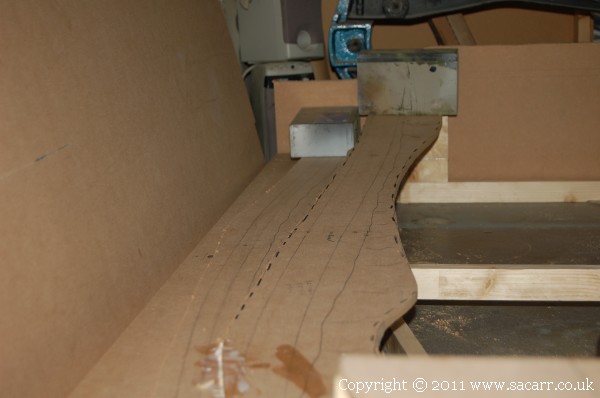
The first step was to jigsaw the boards into strips along the edges of the hillsides, so that each level could be separated.

cstation4.jpg


This close up shows the road to the station bent upwards. This strip will rise much more steeply than the branchline track.

cstation5.jpg
 
These strips are the other branchline climbing to the mine, and the track leading to the airfield.

cstation7.jpg


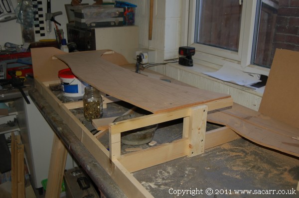
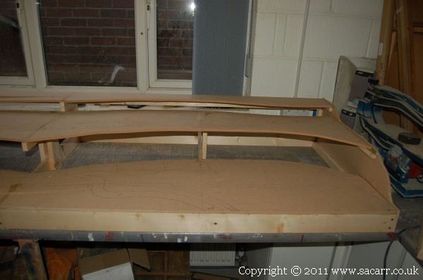
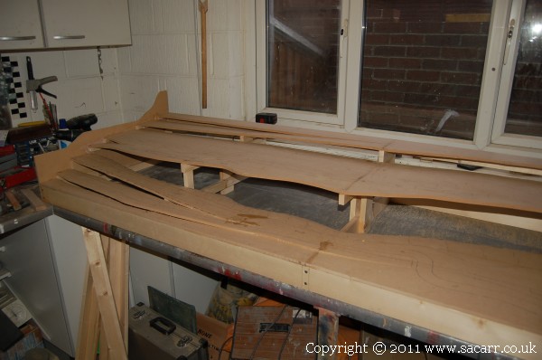
The framework is coming together now. This view is looking from the rear The raised board is the approach to the station. Behind that and lower is the base for the branchline leading to the quayside.

cstation9.jpg
 
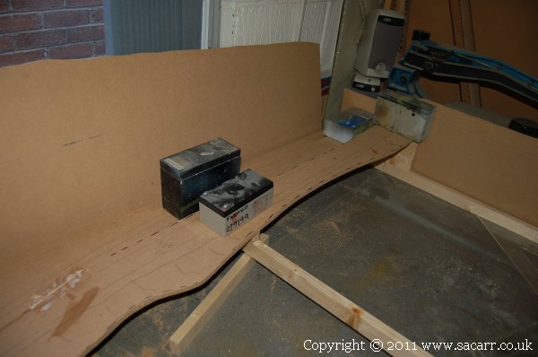
The road and branchline inclines weighted down and drying.

cstation10.jpg


This view shows the difference in levels between the road, track bed and fields next to the branchline.

cstation11.jpg


Affiliate Disclosure: We may receive a commision from some of the links and ads shown on this website (Learn More Here)

Back
Top