ModelRailroadForums.com is a free Model Railroad Discussion Forum and photo gallery. We cover all scales and sizes of model railroads. Online since 2002, it's one of the oldest and largest model railroad forums on the web. Whether you're a master model railroader or just getting started, you'll find something of interest here.
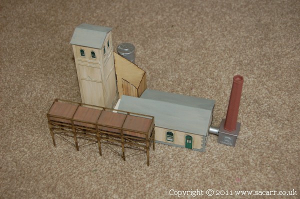
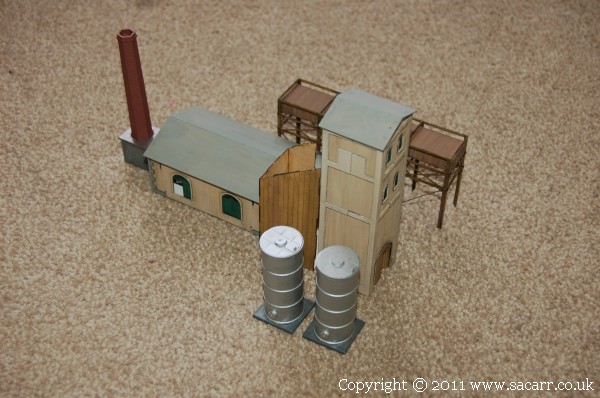
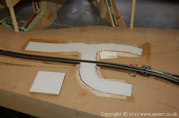
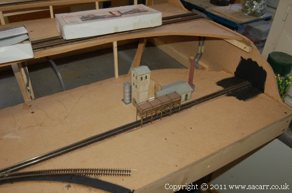
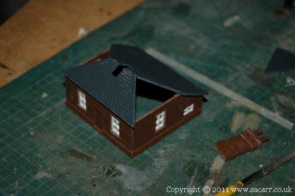
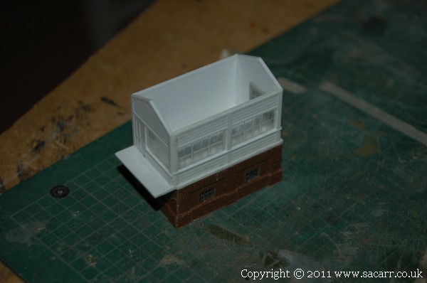
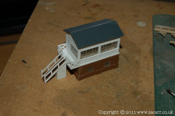
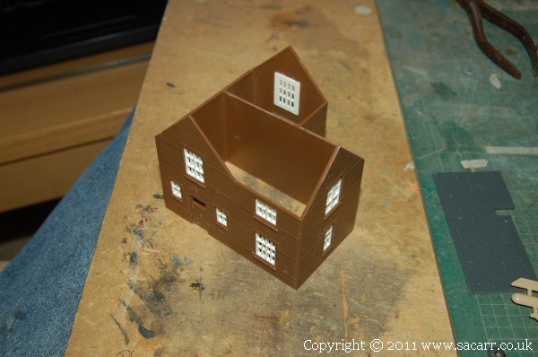
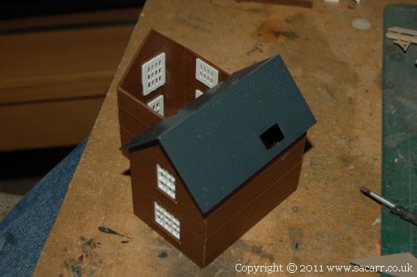
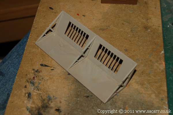
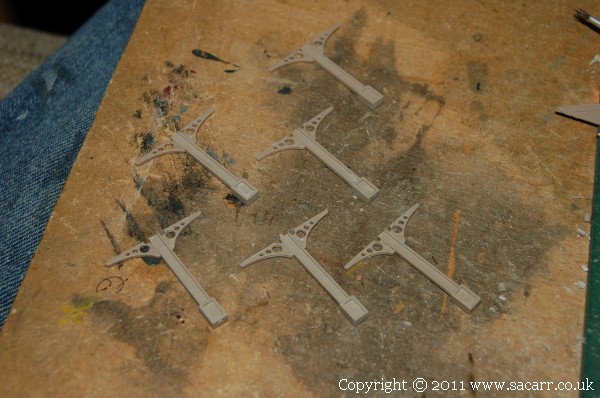
These last two pictures of yesterday bring the build thread to present time. The buildings were placed together for a photo but also to see the foot print of the complex. I needed to get an impression of the floor plan in order to make sure that there is enough space around the structure before scenery is fitted to that part of the layout.
That's it, you're all up to date with the build now, so future posts in this thread will be as they happen on the layout. Apart from finishing this building, I need to solder the track power supply wires to the rails, have a quick test, then it's level crossing and scenery!
The guy that bought my 'Area 51' layout ended up printing the whole thread I did for it. He said he used up several ink cartridges and piles of paper, because with photos, you only get three or four posts onto a sheet of paper! I think printing the thread as a PDF would be a better option!
As soon as I've had a coffee, I'm out to the workshop to start wiring section three.
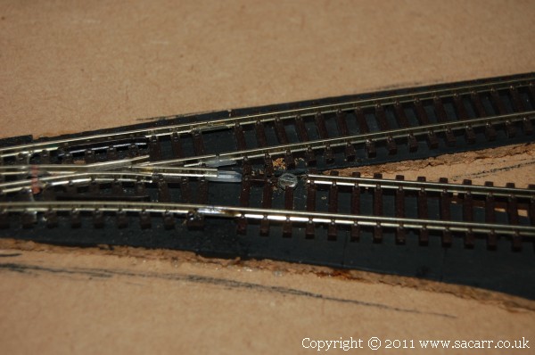
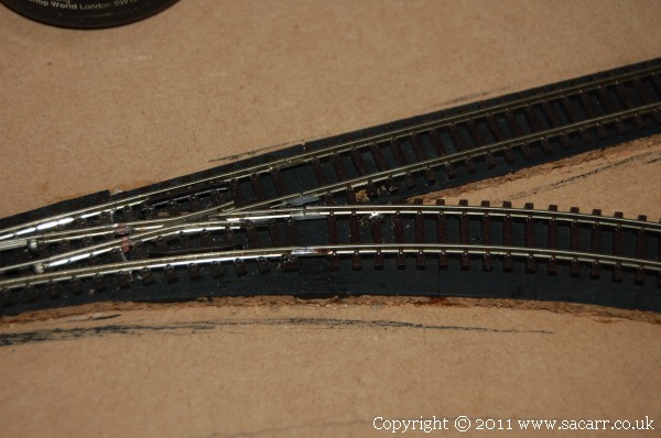
This morning I finished laying the track along the upper branch line, then added a short section of flex track that will curve around from the lower point to the quayside yard. Because it is a fairly tight curve, I wanted to solder the rail to the point to maintain a smooth transition between the two. This was easy on the outer rail as it had a metal joiner. Due to the live frog point, the inner rail joiner was a plastic insulated type, and this was distorting under the side load from the curve in the flex track. To solve this, a tiny screw was put into the track bed, flush with the bottom of the rail, and tinned with solder. The rail was pushed into the rail joiner, aligned, and a small amount of solder applied. The side loads are now taken up by the screw and not the plastic rail joiner.
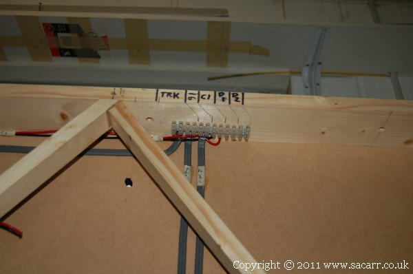
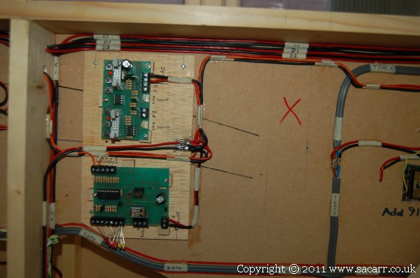
This is the wiring that connects the station section to the quayside yard. The wires end in a screw terminal block, and short fly leads will link the two together once the layout is finally assembled. The two grey cables on the left are the track power ring, while the third is the 16v AC auxillary accessories supply. The red and black pair are the power for the isolated station siding, switched from the instrument panel. D1 and D2 are yet to be connected, but they are the switched track power feeds for the two sidings at the airfield.
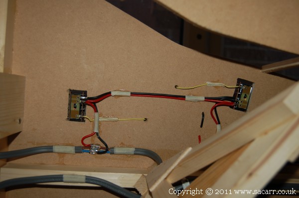
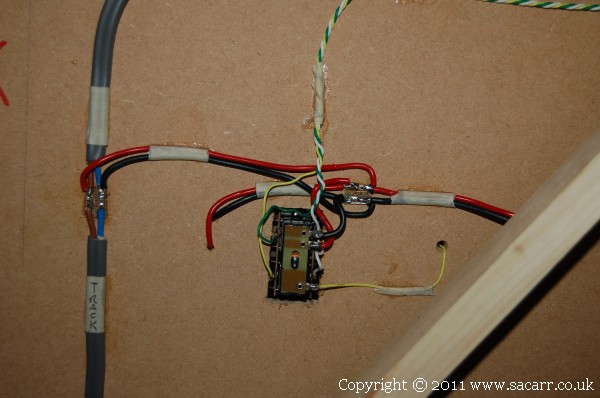
Two of the PL-13 switches can be seen here on the bottom of the point motors. Track power feeds the switches while the yellow wire from the switch feeds the frog.
Left to do is the point motor wiring and installing the DAC20 point decoder when they arrive, along with their power supplies.
The first of the point motors is wired up. Green and Yellow are the direction wires, with White as the common. This will be connected to the last spare output on the decoder on the previous section. The rest of the points on this section and three on the next section will be operated from the decoder going in this section.
Around the layout, I'm running a 240v mains circuit, into which plus the power supplies for the points decoders and any other mains transformers. This keeps the wiring all self contained so we don't have hundreds of extension leads dangling from the bottom of the layout. Each section connects to the next via a normal fused three pin plug and socket.
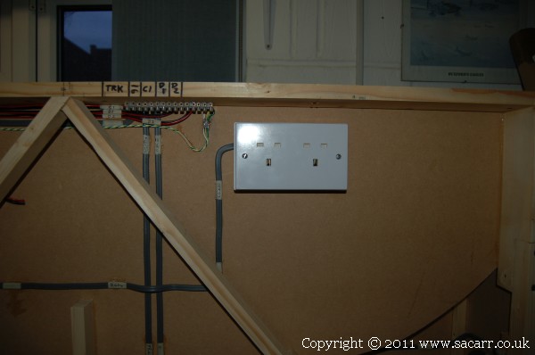
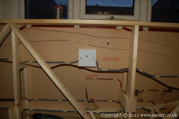
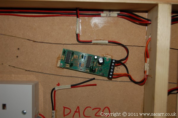
Here's the socket for the DAC20 power supply. The DAC will be mounted to the right of the socket. I've written it on in red to remind myself to keep this area clear of wire runs.
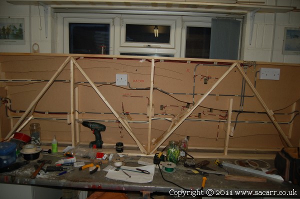
A general view from a bit further back showing all the wiring so far, and a very cluttered work bench. I didn't have time to clear up at the end of the day, just snapped a photo and then had to dash off and collect my daughter from Nursery.
After a morning working in the garden laying more paving stones, I went into the workshop for a rest! So far I've got about 70 out of 90 laid.
The point motor wiring is all complete now, with the five section points wired back to the location of the DAC20 decoder. Three further sets of wires run from this point to the left side board joint, where they will connect to three more points on the next section.
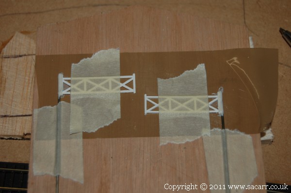
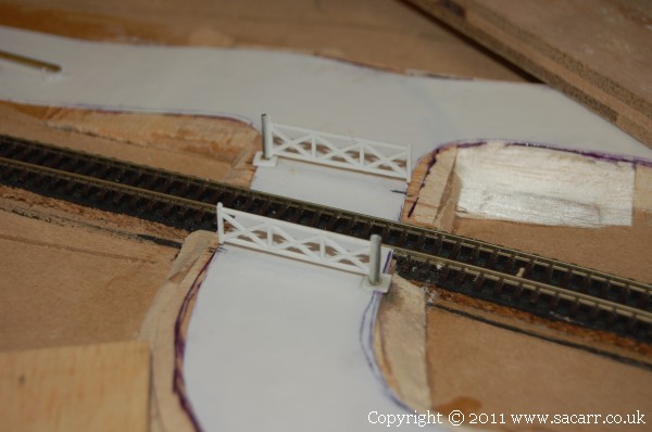
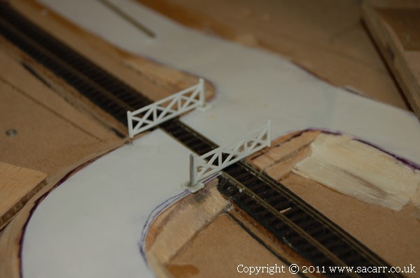
The level crossing comes next, as I need to at least sort out the mechanics that operate the crossing gates before any scenery is done. The side of the gate with the hinges was sanded thinner and a chamfer sanded into the edges. The gates will be driven by a vertical wire through the base board. The gate and the wire was taped down to a flat board covered with parcel tape, and the drive wire glued to the gate with Hysol 24 hour epoxy.
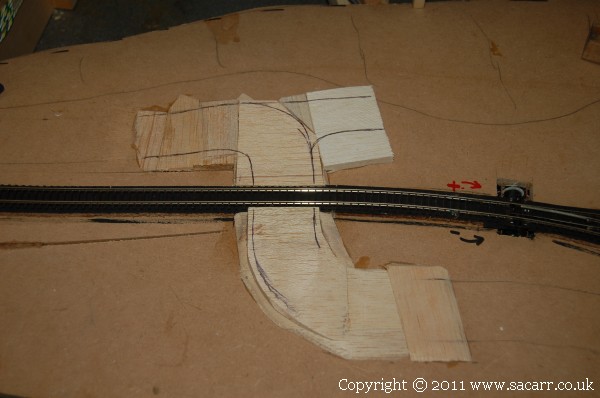
The ground area where the road meets the track was built up with balsa wood sheet, which was then sanded back to blend into the base board. The main road does an 'S' bend across the track, but there will be a small turn off to the right, on the far side of the track, which will lead to the clay works.
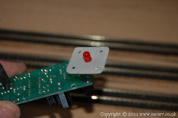
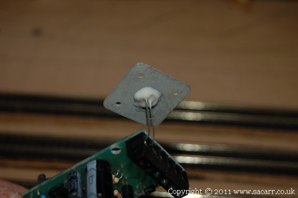
The electronic sensors which will operate the crossing have an LED to indicate sensor operation. I wanted to mount this on the front of the layout, so cut some one inch square aluminium mounts for the LED's. They had their edges filed, and were then sand blasted for an even finish. The LED's were then glued in with Hysol epoxy. The LED's were left mounted in the electronics to both hold them while the glue sets and also because I haven't marked which leg mounts in which hole on the circuit board yet. Fly leads will be added to link the LED to the circuit once both are mounted in the layout.
A little progress from the last few days. The level crossing gates had the glue trimmed ready for installation. The balsa base for the road was skinned with thin styrene which forms the road surface. Two brass tubes were then set into the baseboard for the gates to pivot in. The white rectangle is the base for the crossing keepers gate house.
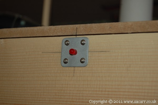
The LED indicator for the sensor was then mounted in the front of the layout.
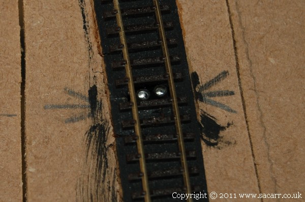
The infra-red sensors fit snugly between the sleepers, and once everything is ballasted, should hardly be noticeable.
While the section was upright, I had a quick test of the clay works into the space left for it. Enough space around it for it not to crowd the adjoining yard.
This afternoon was spent finalising the wiring and making the linkages for the crossing gates. The gates need to be slowed a bit, but other than that, all OK.