Rebuilding Estate Purchased Korber Roundhouse


beiland

Well-Known Member
Quite a few years ago I purchased a combo Korber roundhouse and Diamond Scale turntable 'set'.

The turntable pit was warped, and I had to construct a new one. I posted some details here,...
https://modelrailroadforums.com/forum/index.php?threads/build-your-own-turntable.32492/#post-481527

Then I turned my attention to the roundhouse which I sought to mount on its own metal base plate.


Roundhouse Base Piece


I've mentioned building a base plate for my roundhouse structure before, but was unsure of what material I wanted to use. I settled on a thin sheet of metal I had laying around, and that happened to be painted black. I sought out a thin material so my incoming tracks would be practically the same level as all the other tracks around the turntable.


I intend to mount the tracks and the roundhouse structure all on the same base plate, so it can be lifted off the layout as one piece in order to add additional interior details at a later date, and to get it out of the way while finishing off the via-duct bridge behind it, and the city scene structures and backdrop.


I figured that the thin metal base plate could be made a stiffer by gluing both the tracks and the floor material to the metal base plate. The floor inside there needs to be level with the tops of the rails. The easiest way I could think of achieving that was to use a combination of 2 different material,...one about the height of the ties up to the molded on rail retainers, then a final layer of thin styrene to meet up with the rail tops. I chose some scrap masonite I had to build the first layer of 'floor' . In these photos you can see the 'between the track' masonite flooring.
DSCF5369.JPG


DSCF5370.JPG


The masonite is also relatively stiff on its own, and becomes more-so with fully glued to the base plate. Interestingly I discovered that PVC cement worked extremely well with gluing the masonite to the scratched up metal plate.


I then proceeded to glue up the wall structures of the roundhouse itself. For these operations I used a 5 minute epoxy as I worked my way around the perimeter section by section. The walls are joined to each other, but more importantly the are bonded to both the metal base plate AND the 1/8” tall edges of the masonite floor pieces.
DSCF5371.JPG


DSCF5372.JPG


DSCF5373.JPG


BTW, I cut the metal base plate with a little extra oversize lip that helps with grabbing and lifting out.
 
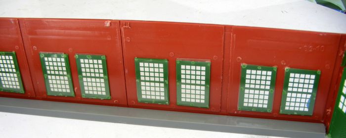
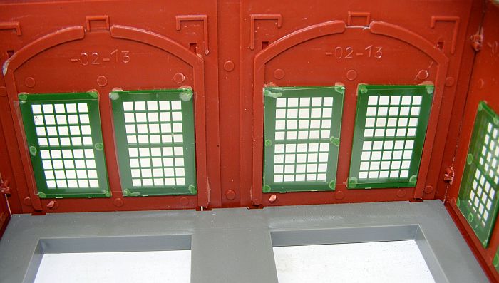
I was very fortunate to be able to remove the window frames from my used roundhouse,...without damaging them. I'm not sure how they were originally put in, but it appeared to be just some sort of minimal tacking method.

So now I am looking for advice on the best way to re-install them once I finishing painting the interior walls, etc?

I assume I would use some sort of tacking method such as these
examples?


Color of the Interior?


I taped up all the window openings so the brick frames would not get recolored, then sprayed the interior with a primer coat. My question,..is my choice of color appropriate? Is it too dark?


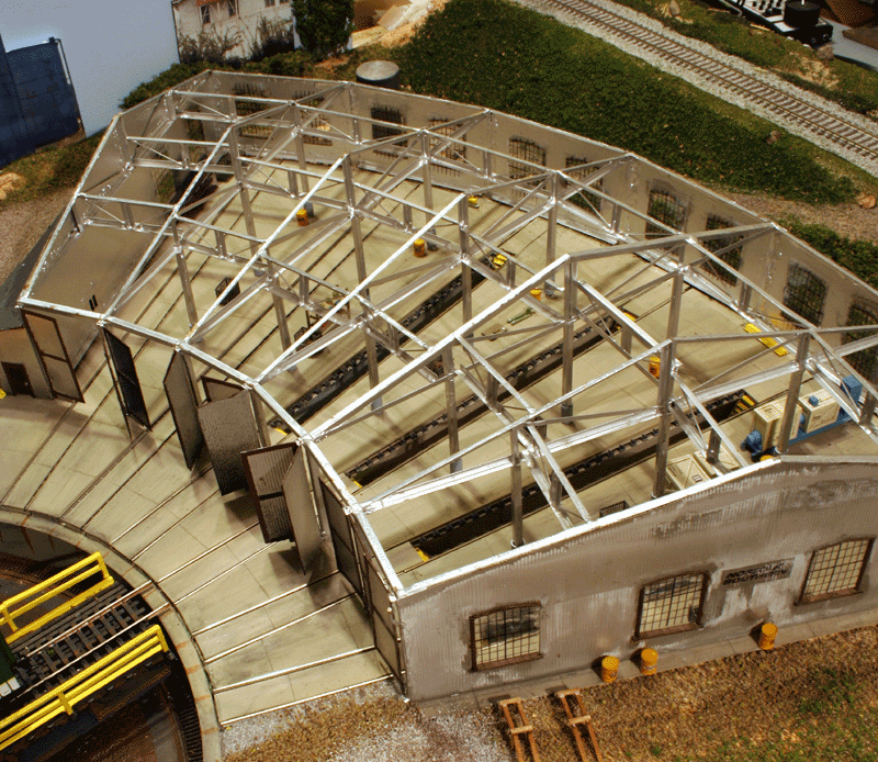
Recall that I am considering leaving the roof off so my steam fleet displays well.


DSCF5495.JPG


DSCF5497.JPG


I want to decide on the final color of that interior because I do NOT wish to have to re-tape those windows again.
 
Last edited:
FWIW - I think that color is perfect. It will look even better with a light weathering maybe of an ink wash?
I know you want to show off the locos, but roundhouses were not clean!

Also, maybe have two stalls with a roof over them?
 
I'm sure they were likely a bit of a mess at times. I hope to put a few 'shop machines' in their from another old kit.

And I'll definitely consider a partial roof, and/or a removable roof as one fellow did.
 
It looks like that the windows were originally installed using liquid cement judging by the spotting around the windows in your example where there is dried cement residue.

Canopy cement with work fine for the re-install as it was suggested in another Forum Thread or again liquid cement like Bondene will work great.

Greg
 
Paper Images of the Pits in the Roundhouse?

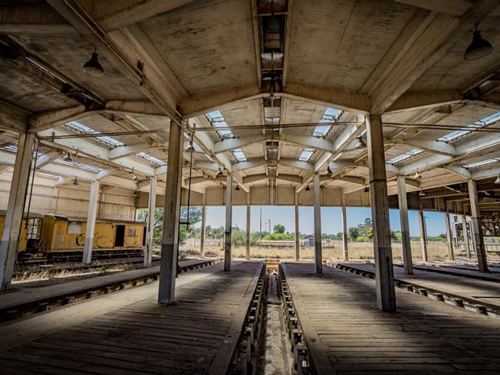
There was a time in the past when I considered cutting the ties between the rails of the roundhouse and making pits in there as would likely be seen in many real roundhouses,....but that would be too much work,..particularly when they would be hidden by the big steamers housed there.

So today I thought why not paper pictures/images of the pits glued in between the rails under the locos. Has anyone seen such a arrangement? Sure might be much easier to do.
 
I am a bit slow on some aspects of this build, but perhaps a little explanation here. I did the first phase of the roundhouse restoration,.....adding the base plate, to be able to assemble all the separate wall sections on my estate acquired (disassembled) structure,...to see what parts I might be missing,...and to see if I was going to be able to make use of this structure,..or look for another one.

Then I set it aside and went to work on other aspects of the layout. I didn't even attach the tracks that came with it as I figured those might need mods etc once I figure exactly how they were going to mate up with the turntable,...and how things were going to be wired.

I had cut my hole for the turntable pit I custom made, but never mounted it permanently. I'm glad I did not as the hole has been rather handy for me to stick a portion of my head up thru while I reinstalling my staging track decks up in that area,.... after laying the track and wiring those staging decks up on my carport work bench
 
Per many observations I've seen, many have the roof in place on their roundhouses, so why go to the effort to have pit details. I've seen a number of photos that show the roof off, and though it looked inviting, so I am seriously considering it,...particularly sense one of my reasons to place a turntable-roundhouse scene right up close to the aisle was to 'display' my collection of large steam engines to both myself and any other visitor that should happen by.


Shame to have all your big steamers in a drawer, or on a shelf, or in staging. I want them 'out front' on the layout. My diesels will be 'hidden' down in staging....ha...ha.


I thought about removing the ties on portions of the track where the pits would be, and just leave it a dark black/dk-color. But I am concerned about keeping those rails in gauge where I remove substantial number of ties. That's where I began to think about leaving the ties in place and masking their existence with an image of a pit.


I gave some thought to making some of the layout both DC and DCC compatible, but then thought about my electrically challenged mind, and some experiences I had on my first major layout, the Central Midland, and thought I want to get on with getting the whole layout up and running,...not spending all my time sorting out electrical wiring.
https://model-railroad-hobbyist.com/node/31007?page=5#comment-465831


https://model-railroad-hobbyist.com/node/31007?page=2#comment-300170


Turntable/Roundhouse on my older layout:
Roundtable Zone
I’ve always favored steam engines for their intricate nature and great variety of forms. So naturally there is a steam engine turntable and repair facility. And why not put this right up front where one’s collection of steam engines can be on display. This steam display replaces the diesel facility of the original Atlas plan. It features:
a) A fully operating turntable capable of handling a BigBoy or Allegheny.
b) A roundhouse, and several different repair shops
c) Outdoor track stowage (nice display of steam roaster)
d) A water tower and diesel fuel tank
e) A twin track coaling tower
f) A twin track bridge crossing to this steam facility from the freight yard.
3%29%20Turntable%20addition%20w%20steam.jpg
 
Wiring my Roundhouse Tracks

I have mounted my incomplete roundhouse on a thin metal base plate for several reasons..
image-20210216231819-1.jpeg


image-20210216231932-2.jpeg


One of the primary reasons was so I could extract it at some later dates to finish it out ,...and to add additional details down the road. For that reason it needed its own permanent base with the internal tracks already installed,...so the whole structure including its tracks could be withdrawn and replaced, at will, in one chunk.


image-20210216232024-3.jpeg


Naturally I need to power those tracks within the round house, but I don't want to do it with individual feeders to each of those tracks,..too many connections/disconnections to make each time. So I'm thinking of ways to wire those tracks together such that I only end up with 2 wires actually going thru to the bottom side of the deck. I'm thinking I can run each polarity wire across the expanse of the five tracks, just under the rails and between the ties, then down thru a single hole in the plywood deck. My solid core, 22 gauge wire will fit just fine. That size wire should be just fine for powering those very short roundhouse tracks.

Does anyone see any problems with that 'series' hook up of feeders wires? Or does anyone have an alternative suggestion(s)??

I also believe I will connect one side of the feeder pair to a toggle switch such that I can turn the whole set of tracks off except when I want to move a loco.


(don't need all those locos just sitting their idling when not in use.) I'm thinking of doing the same toggle cutoff for those outdoor storage tracks as well.
 
Without each track being powered separately you will have all locomotives running at the same time. If they have sound , it could be annoying. I prefer to be able to turn on the track I need.

Couldn't most of them be silent except when addressed specifically?

I have heard that they don't turn off completely if they are sitting on a powered track, but do they have to make noise (or move) if they have not been called on??

The answer is, it depends on the decoders and sometimes their settings.
Behavior like you ask is not standard. Partly because some people and
vendors like the loco to respond right away and others like to go for the
more prototypical where you have to do things to wake it up.

How the vendors give you options about this are not standard either. You
will either have to look into the datasheets for the decoders or use
something like JMRI to figure out how to adjust the loco behavior to the way
you want it.

If someone had not properly stopped a loco before you turned off the power
may leave it in the command station with functions or speed still on. If
power is applied to that loco, it will respond.

The static drain of decoders is very low. The idle sounds of a decoder
consumers more power as would lights. One downside of using a single circuit
for all the round house tracks is the inrush and startup hit all those
decoders would get every time you turned it on to get one of them. Same
issue with power down, some particularly with keep alive may make some
really weird sounds as they discharge after you turn off the track.
My normal suggestion is either leaving the tracks live or wire for
individual control of each track.
-Ken Cameron, Member JMRI Dev Team
 
I have heard that they don't turn off completely if they are sitting on a powered track, but do they have to make noise (or move) if they have not been called on??


Many of the sound equipped locomotive can have their sound turned off when they are sitting idle primarily just for this reason.

Greg
 
Rethink,..no pin sockets and now power to each individual track

I was looking this situation over again today, and arrived at new KISS ideas.
First off I am going to power each track individually as has been suggested. I will attach two feeders wires to each of the 5 roundhouse tracks,...somewhere along those tracks where we might find pits between the tracks (thus hiding those track connections with some sort of pit image glued between the rails).

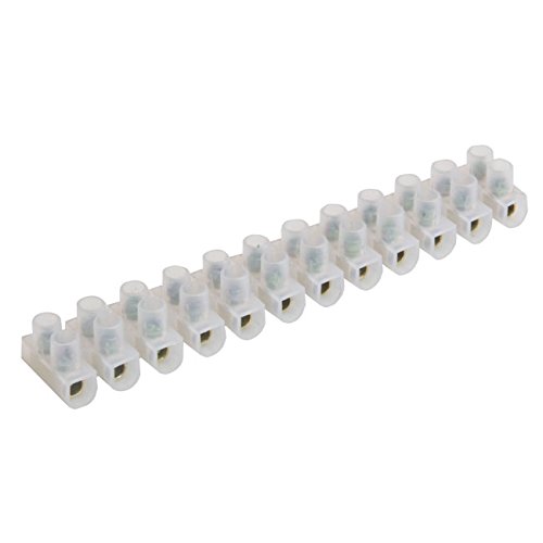
Those 10 feeders will go down thru the plywood deck in generous size holes that will also be hidden by the 'pit image'. Those feeders will be attached to a wire-to-wire terminal strip like this..
Terminal Block Connector Strips | The Tools & Fixings Co.

China 3A 2 Way Screw Terminal Block Connector - China 2 Way Terminal  Connector, 2 Way Terminal Block

When it is desired to remove the structure for detailing it will simply be unscrewing those 10 wires and letting them come up with the structure and tracks as a whole unit. Upon replacement the 10 wires will be fed back thru the holes in the plywood deck, and rescrewed into their terminal spot.

I'll be providing a terminal block for both polarity feeder wires. One polarity will be wired as a 'common wire' and the other will be individually fed to a cut off switch such that each individual track can be cut off or powered up.

I will also be wiring up my other stowage tracks around the perimeter of the turntable in a similar fashion so that each of them can be powered up individually. I have a fair number of them, and I may resort to using a single switch to control 2 tracks rather than just 1.
image%28127%29.png


image-20210223201827-1.jpeg


Back
Top