PRR T1 4-4-4-4 BLI MINIMUM TURNOUT RADII


Hello

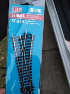
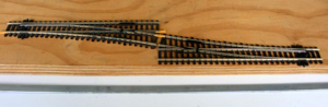
I hope you had a great thanks giving, I have a question regarding turnouts that I was hoping to get some advice. I just purchased the BLT PRR T1 4-4-4-4 and I am reconfiguring my layout to run it. I have one section of track that requires a turnout but I'm not sure given that it will be leading into a straight track whether it will make any significant difference what turnout size I use. I run peco code 100 streamlined and was going to use a 2nd radius left turnout as I have one spare. This equates to roughly 18" but we are only talking a very small turnout


Thanks in advance
 
Per BLI, minimum radius is 22".
I was able to coax mine around very short sections of 20" radius, but it wasn't happy about it.
Thanks for the post. Thankfully I have minimum 24" track for the section I have dedicated to running bigger locos. So the area in question is quite literally just the length of the turnout. I'm glad you were able to use the loco on 20" because the rest of my layout is 21". So there is hope that the loco could work on other parts of the layout. I am assuming at very slow speed?
 
First off I assume you are speaking of a double curved switches by Peco? Peco makes 2 sizes of these,...one of them a very tight radi combo of 22 and 18 (actually slightly less than 18.)

Here is a little discussion were I was considering replacing my Roco double curves with Pecos. You will find that I chose to stick with my original choice of Roco because of the extra tight radi Pecos
https://model-railroad-hobbyist.com/node/41194

I would not put a lot of hope in that large steamer negotiating those tight radi, particularly the inner curve.

You might also visit this discussion
https://model-railroad-hobbyist.com/node/35022?page=3
 
This is just me and my preferences, and I understand that you want to run this beautiful futuristic steamer in the worst way. I get that.

However, this was a slippery, high-stepping, 6000 hp, jackrabbit of a passenger locomotive meant for speed. You will have to slow it to about 20 scale mph to get it around 22" curves reliably. If you could manage even two more inches of radius somehow, you will be able to run this engine across your entire system at 'limited speeds', as in Broadway Limited, Century Limited, and all those high varnish passengers trains of the 1940s.

Note that this engine, at least it is the case in my original Paragon version of 2004, has both central driving axles 'blind'. There are no flanges on those drivers. So, on turnouts less than about a #10, or on curves less than about 45" radius, those axles will end up well inside the rails along those curves.

Note also that my Paragon version, even with four blind drivers, is among my very best pullers.
 
Thanks for the advice I will follow it up. Also the curves are flex track measures
This is just me and my preferences, and I understand that you want to run this beautiful futuristic steamer in the worst way. I get that.

However, this was a slippery, high-stepping, 6000 hp, jackrabbit of a passenger locomotive meant for speed. You will have to slow it to about 20 scale mph to get it around 22" curves reliably. If you could manage even two more inches of radius somehow, you will be able to run this engine across your entire system at 'limited speeds', as in Broadway Limited, Century Limited, and all those high varnish passengers trains of the 1940s.

Note that this engine, at least it is the case in my original Paragon version of 2004, has both central driving axles 'blind'. There are no flanges on those drivers. So, on turnouts less than about a #10, or on curves less than about 45" radius, those axles will end up well inside the rails along those curves.

Note also that my Paragon version, even with four blind drivers, is among my very best pullers.
Thank you for your detailed post. I will be running it on 24" curves. The points in question will only be used to switch from one straight track to another running parallel.. Here is a picture of the turnout . I am only considering using it because I have one at home. I am happy to purchase another if it will do a better job.
First off I assume you are speaking of a double curved switches by Peco? Peco makes 2 sizes of these,...one of them a very tight radi combo of 22 and 18 (actually slightly less than 18.)

Here is a little discussion were I was considering replacing my Roco double curves with Pecos. You will find that I chose to stick with my original choice of Roco because of the extra tight radi Pecos
https://model-railroad-hobbyist.com/node/41194

I would not put a lot of hope in that large steamer negotiating those tight radi, particularly the inner curve.

You might also visit this discussion
https://model-railroad-hobbyist.com/node/35022?page=3


Thank you so much for the post, I will follow the links.
 
This is just me and my preferences, and I understand that you want to run this beautiful futuristic steamer in the worst way. I get that.

However, this was a slippery, high-stepping, 6000 hp, jackrabbit of a passenger locomotive meant for speed. You will have to slow it to about 20 scale mph to get it around 22" curves reliably. If you could manage even two more inches of radius somehow, you will be able to run this engine across your entire system at 'limited speeds', as in Broadway Limited, Century Limited, and all those high varnish passengers trains of the 1940s.

Note that this engine, at least it is the case in my original Paragon version of 2004, has both central driving axles 'blind'. There are no flanges on those drivers. So, on turnouts less than about a #10, or on curves less than about 45" radius, those axles will end up well inside the rails along those curves.

Note also that my Paragon version, even with four blind drivers, is among my very best pullers.
 

Attachments

  • IMG20201201204125.jpg
    IMG20201201204125.jpg
    441.5 KB · Views: 119
I run peco code 100 streamlined
Chef, what you picture there is a SET TRACK turnout made by Peco,...not a STREAMLINE one made by them. Be aware they are two different items. The set track items are generally all of a tighter smaller radius.

The turnout you pictured is also not the 'double-curved' one I thought you were speaking of. It is a convention left or right hand turnout.

Are you speaking of routing your engine from one straight track over to another parallel track?.....thats a crossover requiring two opposing turnouts of the same type??
 
Your T1 will never operate through the turnout part of that Peco switch. I am in the process of removing all Peco turnouts from my layout, since they are completely incompatible with any of my larger steam locomotives--including my T1.
 
I did quite a bit of experimenting with all sizes of Peco turnouts,...and with steam engines. I did not find that much of a problem with them for the most part. I did find problems with the smaller range such as the 'Small' size streamlines and longer wheel based steamers. They require a shim in that guard rail across from the frog.

Here is one of those test, https://model-railroad-hobbyist.com/node/35913

Here is another,..... https://model-railroad-hobbyist.com/node/40852
 
Thank you to everyone who has contributed to my post and for the wealth of information you have provided, it is very much appreciated.

I guess for me this is the second layout I have put together. The first was very simple as it ran in a large oval shape and was not very complex in terms of its operation. I was very disciplined in not purchasing loco's that would challenge the layout to maintain smooth operation. I was only interested in aesthetics at the time, so I did not invest a lot of time learning complex tracking systems and point connections and so on. Therefore my understanding of the different points and their proper function is limited. Thank you for pointing out the differences as I now come to realise I am running a mixture of both. Luckily the points running on my mainline are all to like (streamlined).


The link you provided to your discussion regarding the different point systems was very helpful as you happend to identify what I am trying to achieve (see picture attached). All the locos I operate have been designed for 18" track operation, the PRR T1 4-4-4-4 is the exception. It's such a magnificent looking loco I was happy to make alterations to run it.

My question is related to the best function of the point link pictured so it will not cause the loco any grief during basic operation. As previously mentioned I have designed a dedicated track to run this loco, which runs on 24" curves and this is the only point sequence this loco will use on the section of track it will operate on. I would rather purchase the right track whilst I am still designing my layout. Would you suggest I go for a wider arc radius and add a straight track link in between for smoother easement through the points, or will having a direct link of the two points as pictured below will suffice? Also what points would you suggest, because I wasn't sure I could mix brands without running into electrical issues.


Note: I love the fact that you have moved away from electric point operation systems, as I too have been considering removing all my point motors in favour of a more challenging design experience of running a manual point operation system. Some of the ideas you have discussed has got my mind buzzing with possibilities.
 

Attachments

  • image(31).png
    image(31).png
    340.3 KB · Views: 116
Last edited:
What you want is an HO #5 turnout or a #6. I use Peco Streamline Code 83 HO #6 turnouts widely on my layout, while the rest are hand-built # 8 turnouts or custom double-slips and 'curved' turnouts, meaning both routes curve the same direction.

The Paragon T1 will easily handle a true #5 turnout. You have choices from Micro Engineering, Atlas, and probably Peco as well. Here is mine from a layout torn down in 2012: That's a hand-built Code 100 #6 double-slip beside the steamer.

index.php
 
Thanks for the post. The info was very helpful. As it happens I have been using #5 turnouts without realising it or knowing the difference. This is due to purchasing based on available space rather than fully understanding correct operational track planning .

Would it be a problem if my layout consists of Peco flex track and points to incorporating Atlas or Micro engering track if the coding match's I.e code 100? Or will their be operating issues?

By the way, the Loco in the photo is a beauty, and your layout looks incredible. You mentioned tearing this one down, have you up sized, down sized or just not running a layout at home anymore? And are you happy to share more photos?
 
A couple of pointers: Some of the Peco Code 100 turnouts have guard rails that are spaced slightly more from the stock rails than for American HO scale. As a result, on the diverging route, the flanges of locomotives and rolling stock may "pick" the frog point. The solution to that, where necessary, is to cement a .010" shim (metal or plastic) on the side of the guard rail that faces the stock rail.

As you probably know, the Pennsy had problems with the T-1's on sharp curves. So they confined operations to straighter track, IIRC, on the New York to Chicago runs (that may not be correct).

I have no idea what the rigid wheelbase of your T-1 model is, but I have four ten-coupled, kitbashed locomotives, two each, 2-10-2 and 2-10-4's that will negotiate 18" radius curves, and Atlas Custom turnouts with no problem. The wheelbase measures 3.250" axle-center to axle-center, with 63" scale diameter wheels. The trick on those is only the end driving wheels are flanged. All drivers in between are blind (flangeless) and shimmed above the tops of the rails by .010", so as to prevent the wheels from catching the inside of the outboard rail coming out of the curve. Don't know if that would be any help, since I don't know if your drivers are sprung or fixed.
 
I appreciate the comments. Means a lot. I am most of the way through a somewhat larger track plan layout, this time with twinned mains. I'm just about to start laying ground material around the tracks in the yard.

In both cases, the yard soil is actual garden soil dried in a paper bag for a couple of weeks, then sifted through pantyhose. Later, mix it with some plaster of Paris so that when it is wetted, it will harden and stay in place and be durable. I also wetted it with a yellow glue solution, diluted 1/6, to help make it even harder. After it was groomed, rolled, wetted, and set in place, I sprinkled Woodland Scenics 'cinders' here and there to get the dirty industrial look.

You can match different brands of track and turnouts (points), but it takes some care and attention. The two main factors to get right are both on the rail heads. I mean the top bearing surface and the inside flange face right next to it. If you get those two matched to within 1/4 millimeter, you'll have few problems. But, let your rolling stock be the tattle-tale. Before you permanently affix your track elements, run everything you own over them, trailing and shoving, forwards and in reverse. Also, at 80+ scale mph. You want to be thoroughly happy that you won't have any 'shelf queens' in rolling stock that can't be run because your trackage doesn't work for them.

One final bit of advice: some looking ahead now might avoid some disappointment later. Almost none of us stay with one or two locomotives and a few freight cars. Not for long. Eventually, you'll want something that demands wider curves, fewer S-curves, or maybe even wider clearances to the sides of the tracks so that longer rolling stock won't snag a rock face or a loading platform set too close. Anything you can do now, while you're still figuring and planning, to widen curves, avoid sharp S-curves (cross-overs, for example), or make your 'gauge loading' wider, you will at some point be thankful for. It might be 12 months, it might be 24 months, but you never know.

Another set of photos from that very satisfying layout:

index.php


index.php


index.php
 
Funny you should mention the widening of curves. I literally pulled up all my curves today and widened them to 24" the whole way round. this has caused problems with my layout configuration so its back to the drawing board on certain sections of track, but oh well, I think you are right that the work will pay off later and I will be less restricted.

Your layout looks great, the realism is something I can only hope to achieve. I use ground coffee that I have dried over several weeks to use as earth. I love the idea of mixing it with plaster of Paris. Never thought of doing that. How do you wet the mixture, do you pre-mix it before applying?
 
A couple of pointers: Some of the Peco Code 100 turnouts have guard rails that are spaced slightly more from the stock rails than for American HO scale. As a result, on the diverging route, the flanges of locomotives and rolling stock may "pick" the frog point. The solution to that, where necessary, is to cement a .010" shim (metal or plastic) on the side of the guard rail that faces the stock rail.

As you probably know, the Pennsy had problems with the T-1's on sharp curves. So they confined operations to straighter track, IIRC, on the New York to Chicago runs (that may not be correct).

I have no idea what the rigid wheelbase of your T-1 model is, but I have four ten-coupled, kitbashed locomotives, two each, 2-10-2 and 2-10-4's that will negotiate 18" radius curves, and Atlas Custom turnouts with no problem. The wheelbase measures 3.250" axle-center to axle-center, with 63" scale diameter wheels. The trick on those is only the end driving wheels are flanged. All drivers in between are blind (flangeless) and shimmed above the tops of the rails by .010", so as to prevent the wheels from catching the inside of the outboard rail coming out of the curve. Don't know if that would be any help, since I don't know if your drivers are sprung or fixed.

Thank's for the advice it is very helpful. I will need to check my points to see if I have the issue with the guard rails. I haven't picked up the Loco yet I ordered it last week, so i'm uncertain of all the specifics but I think at this point it might be wise to wait until I can test run the loco and see what issues arise. At least you have given me something to consider.
 
Articulated locos should have less problems than locos with a number of big drive wheel all in a row.

Go to the peco website and get some FULL SIZE paper templates of their turnouts, then use them in your track planning.
I laid down some brown paper (like they use to protect floors during home/office-construction) and drew pencil lines and used those switch patterns to lay out my layout. It was fun doing it that way.
Full Size Paper Templates
 
Yes, mix the dry ingredients well, then spread them as best you can. It will be lumpy. I used a small glass baby food jar to roll it out smooth, and I forget what else I did to try to make it look 'lived in'.

Then, I sprayed it with 70% alcohol in small patches so the alcohol wouldn't evaporate too soon before I applied a spray of the light glue mixture. Note that the glue solution also has two drops of liquid dish detergent to help break surface tension wherever it is applied. Important. The isopropyl alcohol does a good job at first doing that, but it doesn't penetrate as far as the glue will because it dries so quickly.

I always, but ALWAYS, draw a scale diagramme first when planning a layout. This initially confirms the concept. Then, I go to the cleared space and lay out the edges of all the benches with 3/4" cheap masking take. Next, start at a measured spot, per the plan, and commence using the same tape to mark out all the curves and tangents. Use a length of lath to fashion a trammel with a small hole every inch and an end-pin for a swivel point for the curves. When it comes to points, USE A REAL TEMPLATE!!!!!!!!!! Beiland suggests this, and it is about as vital as could be. People fool themselves when it comes to figuring where a point is going to go, how long it is if it's commercial, and how much the diverging route actually diverges. If you bugger this up, your entire track system will suffer, and so will your enjoyment.


Back
Top