ModelRailroadForums.com is a free Model Railroad Discussion Forum and photo gallery. We cover all scales and sizes of model railroads. Online since 2002, it's one of the oldest and largest model railroad forums on the web. Whether you're a master model railroader or just getting started, you'll find something of interest here.
Anyone heard of this hand held remote control unit? Made by an old firm
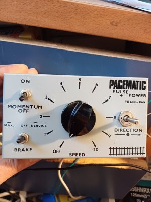
TRAINPOWER, INC. The small rectangular remopte is wired with a single cable that has black, red, green and white leads. There is a knob to regulate power labelled zero to nine and three miniature switches...each has arrows showing direction; one is up and down with the lettering MOM DIR; one points right and left and the last is an up and down position labelled SRV and DSV. Probably 20-25 years old. Help! franklyn Elliott 796-424iott@optonline.net
MOM+ Momentum, DIR=Direct
Right and left will be direction
SRV=Service? (Braking), DSRV = (Probably) emergency brake (Use in MOM mode)
Two of the wire will be power in, 2 will be power out. A guess says that red and black feed power to the track and white and green take 12 volt DC power in. Without looking inside it could take 16vAC in and put 12vDC out
This is all a semi-educated guess from something similar that I had here in UK made by a firm called CODAR, many years ago
Shortliner(Jack)away up here in the Highlands
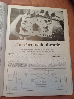
I remember it advertised in the Model Rail magazines back in the 60's. In fact the circuit was designed by Peter Thorne (now deceased) and published in one of his how to do it books. I've built several of them back then and they were ok. I have all of Mr Thorne's books, what is it you want to know?
Cheers Willis
Hello, I have five of these Trainpower Pacematic Throttle PMT-1 units that I used to use with a fairly extensive HO layout. The throttle worked well with the older open motors of PFM or hobbytown units as well as with those smaller closed can motors.
I believe that they could be purchased in kit form or as built units. I soldered 4 of them together.
They had a rotary throttle, 1-switchable momentum, 2-direction, & 3 brake /quick service brake. & I’m pretty sure that it had low speed pulse that faded out at about 50% throttle.
It has literally been since about 1985 since I hooked them up though and I can’t seem to find the instruction sheet for connection info.
There are 5 colored wires in the cable, Black and White are for the output to the track. But my issue is that there are three other wires for the input end. It has an option of some to be able to be hooked up to AC via input through a bridge rectifier but mine were setup for fixed DC input. Red, Orange and Green with red and green being the input wires for the DC. The green appears to be the positive and the red the negative. (I’ve yet to figure out the orange wire. It could be a fixed 12v output. ) I do know that these were being made in the early 1980’s and were priced at about $25 each. and came out of Vienna, Virginia. You could buy them as kits or pre-assembled with or without a bridge rectifier for 112V AC input as mentioned. These units are about 3" by 4".
The mom/dir. is for momentum or direct basic 12v variable current. Center is directional w/center off. The right switch works as a brake with service up and quick service down and center = normal running or brake off.
George's trains in Toronto sold me one of these pictured below in the mid 70s! It was written up in MR..yours seems similar. I wonder what that extra wire is for....I'm not much of an electronics expert.....but Im going to try building another !
George's trains in Toronto sold me one of these pictured below in the mid 70s! It was written up in MR..yours seems similar. I wonder what that extra wire is for....I'm not much of an electronics expert.....but Im going to try building another !
Thanks for replying. That looks very similar in function. Since my post above, I've found the basic wiring for these throttles. (but not that extra wire.).
Back when I was using them in the 80's, I had a layout with 4 of the 5 controllers functioning. One was a spare. Two of them were pre-assembled and I wired up the other 3 kits with their printed circuit boards. They could handle multi-engine trains with those 1950's era DC motors. & are still usable with that equipment. I'm eager to build something and don't really need to go DCC.