ModelRailroadForums.com is a free
Model Railroad Discussion Forum and
photo gallery. We cover all scales and sizes of model railroads. Online since 2002, it's one of the oldest and largest model railroad forums on the web. Whether you're a master model railroader or just getting started, you'll find something of interest here.
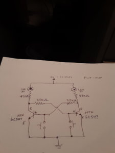
I'm attempting to build a flip flop circuit to indicate position of remote turnout switch to siding. This circuit works great except the 3 volt leds I'm using bleed through when not powered. I'm not sure how to stop the bleeding.
you can paint the sides with a dark colored paint, if the bleed through is coming from the other LED
Do you mean light is bleeding thru or electrical current is bleeding thru?
you can paint the sides with a dark colored paint, if the bleed through is coming from the other LED
No, the led it self has a slight glow when not selected.
Do you mean light is bleeding thru or electrical current is bleeding thru?
I would guess electrical current is bleeding through causing the led to have a slight glow when not selected.
-
20200125_131522.jpg
72.1 KB
· Views: 292
I am NO electrical genius, but could increasing the size of the resistor do it? Maybe 1000 ohm instead of the 470?
I am NO electrical genius, but could increasing the size of the resistor do it? Maybe 1000 ohm instead of the 470?
I tried 1k resistors, but still some bleeding.
You left out the capacitors.
Your circuit will always allow current through the LED.
base to emitter is basically a diode. So the left LED is in series with the right 'diode' completing a path for current.
Increasing resistor does not help since it cannot drop voltage until current flows, so it appears as a short for the nanosecond after DC voltage is applied.
http://www.talkingelectronics.com/projects/5-Projects/Projects16.html
Putting the LEDS aside. How is the switch thrown, by hand, with a tortoise, etc. I have about 10 tortoises with LED indicators attached a they work fine. I light the LEDS with the tortoise's internal switches # 345 / 567.
George
Putting the LEDS aside. How is the switch thrown, by hand, with a tortoise, etc. I have about 10 tortoises with LED indicators attached a they work fine. I light the LEDS with the tortoise's internal switches # 345 / 567.
George
That sounds great. However I have to use Atlas snap switches. I built my benchwork using 1-3/8" thick solid core oak doors with 2" foam board glued on top, making my total thickness of 3-3/8", which the wires with the tortoise are too short.
which the wires with the tortoise are too short.
I'm not sure what you mean? Then solder on longer wires. The wires I soldered to the tortoise internal switches are a least 12'' long maybe longer depending on where I have the LEDS positioned. George
I'm not sure what you mean? Then solder on longer wires. The wires I soldered to the tortoise internal switches are a least 12'' long maybe longer depending on where I have the LEDS positioned. George
View attachment 43730
The wire I am referring to is the actuation wire from the tortoise to the snap switch, not the electrical wires.
The wire I am referring to is the actuation wire from the tortoise to the snap switch, not the electrical wires.
But what's that have to do with the LEDS. Their on their own circuit. In the above photo the yellow wire is on one side of the circuit and the red and green the other. So when the switch is thrown the red LED is lit and when it's reversed the green LED is lit. No Flip Flop needed. Post a photo of your setup.
George
Traingeek344- I've been studying your diagram for the past few days and figured out what is going on. Like dennis461 said, current is traveling throught the "off" LED to the base-emiter of the transistor to complete the circuit. The simplest way to fix this circuit is to allow current to bypass the off LED and keep the voltage below 3V. I don't have a sketch to snap a phot of, so I'll try to describe the changes.
First- add a resistor of 1.6K ohms in parallel to the LED and 470 resistor.
Second- reduce the resistence of the 7.5k resistors to 5.6k ohms.
That should hopefully not change the operation of the circuit and keep the off LED OFF.
p.s. I'm assuming the coils for the switch are not part of this circuit.

Affiliate Disclosure: We may receive a commision from some of the links and ads shown on this website
(Learn More Here)
