Help Please....design a dbl-deck layout in its own Hand-House shed


Don't know if I worded this correctly, but I am wondering if when a layout is operating in DCC, is there a method to automatically stop 2 trains from entering in a common stretch of track?...Can I block one of the 2 trains that might enter the 'common' track at a single moment?...automatically??
The short answer is, yes. The long answer is that there are many ways to do it, all of which are fairly complicated. Some sort of block occupancy or train passing detectors, a stopping mechanism that could be a computer control, a restarting mechanism, interlocking with the switch tracks that would route a train into or out of a "danger" zone. It could be all electronic, all computer, all mechanical, and all combinations thereof. Each method would have its own pros and cons.
 
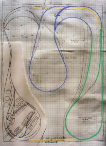
Like your port scene layout.
Turns out, as someone on another forum pointed out, that I have at least 2 turnouts in there that are dbl-radius, and just too darn tight.
I drew them in free-hand. I looked up small radius turnouts and it certainly looks as though I can NOT fit that particular plan. Have yet to figure a modification to that plan that might make it work.

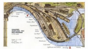
I found what might be a good alternative. This plan looks like it might fit into that 'tear-drop' shape of my layout,...with a little alteration ?
Coalport MD 1941_Plan.jpg
 
New Loop Renditions

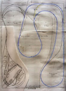
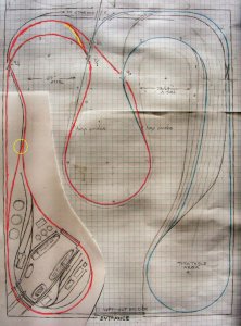
As I've indicated I am not much of a 'apps' person, but this morning decided to just try a paint program to display the individual loops of the track plan,...crude attempt, but it gets the message across.

You will find I have 3 loops of track on the lower level:
1) the one associated with the turntable area (in blue)
2) the one associated with the port area (in red)
3) the one that circles the entire perimeter of the layout when the removable bridge at the entrance is in place.

I have also high-lited (in yellow) several small sections of track that allows for the trains to reverse their directions on their individual loops. This is particularly important on the blue loop to be able to climb onto the helix. I also thought it was important in general.
Roundhouse Loop, ps800.jpg


Port Loop, ps800.jpg
(BTW, forget that port scene as shown, that has to change)
 
Last edited by a moderator:
Ian Rice designed some really attractive layouts. A main feature of his designs is a virtual lack of straight tracks. Switching yards, as shown in that picture, are better with straight tracks, particularly where coupling/uncoupling is going to occur with such couplers as Kadees, which, if mounted correctly, will self center and don't like to be pushed together at the resulting angle induced by curved track.
 
That looks like an Ian Rice design.

You are correct. I found it on google images
https://www.pinterest.com/pin/824369906762356932/

I had a little 'rethinking' last night (while under the influence of a little flu fever) . I'm thinking perhaps I should locate a (condensed) steel mill scene in that loop where I have the port presently? I have some very nice built up and weather steel mill blast furnace etc buildings that I would like to incorporate on the layout. (I was quite amazed when Walthers came out with that model,...hadn't seen anything that extensive before. i bought one set, then sold that off before ever building it, thinking I'll never use it. Then about a year ago I ran into an already built and weathered and lighted one,...couldn't resist)

Then maybe find a way to move a port scene to the head of the peninsula?

BTW, Iron Horseman, I have not forgotten to answer your posting on the 'block occupancy', I just haven't finished my presentation yet.
What track plan software did you utilize to make those original dwgs??
 
Last edited by a moderator:
What track plan software did you utilize to make those original dwgs??
That is just Atlas "Right Track" version 8. Very limited in what it can do, but I can throw stuff together with it really quickly. I use it for thinking through designs because I can cut and rebuild sections of track instead of having to think through all the Bezier curves used in the other track planning software titles.
 
Last edited by a moderator:
That is just Atlas "Right Track" version 8. Very limited in what it can do, but I can throw stuff together with it really quickly. I use it for thinking through designs because I get all confused with things like 3Dplanit, et.al.
I'll have to look that one up. I read thru this whole very long, highly praised subject thread on SCARM, but I got confused right from the get-go about how to ID & select all the icons to get started. I found it easier to just sketch it out by hand.

But the computer design programs can show you were you've made a mistake. For instance the gentleman who designed the original Anon & Muss pointed out the some of turnouts in the port scene I drew up were impossible tight,...too small of a radius. So I am going to have to change that.

Last night I was rethinking and said why not put some of my steel mill structures in that loop area, and make a port scene on the head of the peninsula??

Would that Atlas plan tell me some pretty good approximations as to whether I can find some of that yard scene I drew in lightly shaded, fit in??

I actually determined that you pretty much nailed my idea right up front with those illustrations you posted (other than some details of the side tracks, etc). And particularly when we were just getting started with some ideas.
 
Power Blocks to Prevent Collision

reply Iron Horse

You will find I have 3 loops of track on the lower level:
1) the one associated with the turntable area (in blue)
2) the one associated with the port area (in red)
3) the one that circles the entire perimeter of the layout when the removable bridge at the entrance is in place.

Both of the loops share some track with the perimeter track, so if one was trying to run trains on all 3 at the same time, there would have to be a way to block the outer loop train from moving into a section occupied by those loop trains. I've got a general idea of how to make it work, but I don't know the specifics on the electronics, etc Perhaps I'll do a 'color' presentation......back to that paint program.

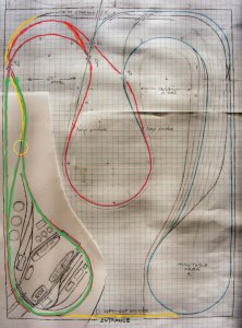
As I said I have a 'perimeter loop' in addition to those 2 inner loops I high-lighted above. But both of them share some track with the perimeter loop. If I had the lift-out bridge in place and desired to try and run 3 trains at the same time, I need some power blocking technics to prevent collisions. The way I see it is my 2 loop trains have the right-away over the perimeter train in all cases.

So I need to block power to the track sections marked here in gold whenever there is a train in the green sections of those loops.
Power block for port loop
Restrctive Power Blocks for Port Loop, ps800.jpg


Power block for turntable loop
Restrictive Power Blocks for Roundhouse loop, ps800.jpg


I'm not really hot on the electronics of this, but isn't there a basic detector that would sense when a locomotive was in the green sectors of either of those inner loops, .....and then an 'interupter' to cut power in those gold sectors? In DCC mode wouldn't you only have to interupt one side of the main bus-line for those gold sectors??

Brian
 
Would that Atlas plan tell me some pretty good approximations as to whether I can find some of that yard scene I drew in lightly shaded, fit in??.
It wouldn't "tell you", it just wouldn't let you do it. The really big problem with the Atlas right track is that it only has Atlas track. The current Atlas catalog has no curved turnouts in it, and that greatly limits what can be drawn (not to mention the limitations of radius for curves only 15, 18, 22, and 24!). For seriously drawing up a plan on the computer (unless one is only using Atlas track) learning one of the other software titles is probably a good idea.
 
The way I see it is my 2 loop trains have the right-away over the perimeter train in all cases.
That is OK, but when doing this one would still have to account for the situation where a perimeter train has already taken the way and for some reason is 'in the way' of one of the others. A bigger issue might be on the other end when the perimeter train is supposed to go from the shared track back to the perimeter - how does it remember it was a perimeter train and take the correct route.

I'm not really hot on the electronics of this, but isn't there a basic detector that would sense when a locomotive was in the green sectors of either of those inner loops, .....and then an 'interupter' to cut power in those gold sectors? In DCC mode wouldn't you only have to interupt one side of the main bus-line for those gold sectors?
Yes, there are basic detectors that know when a locomotive is present. They do it by detecting the current draw of that section. I think every DCC vendor makes some variation of this unit. And yes a simple relay with SPST contacts on it could interrupt the power to the rail. It is a simple scheme. The issues with it are that it only knows where the locomotive is and hence the front of the train (one can remedy this by using lighted caboose, or resistors on the wheels of the cars). A bigger issue, at least to me, is that the train in the controlled block will basically slam to a stop. Slamming to a stop can derail cars and cause unwanted uncoupling. Likewise when the track ahead becomes clear it will slam back to 'full' power. Running trains slowly, keep alive and BackEMF features on decoders can be used to remediate some of this.

And the 3rd yes, Interrupting one side of any electrical circuit (the bus in this case) is enough cut the power and stop the unit.
 
I looked up the Atlas planning software, and it appears to be a version of SCRAM, likely limited to Atlas track products exclusively,...and as you said certain set radius and no dbl curved turnouts.

There is a fellow from NZ over on another forum who just today posted a view of my layout utilizing what I believe is a more advanced version of SCARM. My layout will fit in that shed according to him. (and I think he has lots of experience with building layouts). I'm presently asking if he will help me develop mine further.

One thing that keeps annoying me is the constant repetitions about my narrow aisles., and that I should get rid of my center peninsula. I know they mean well, but I will bet $100 that they are ALL overweight like many Americans, and probably can NOT bend over and touch there palms on the floor, which I do as an exercise every morning and evening. And how many of them have a 36-37 waist at my age.

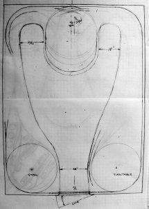
I'm just not ready to forgo my peninsula. I can deal with an 18" neck-down to get back to the root of that peninsula.
 
Computer Rendering

On another forum there has been a gentleman who offered a computer software rendering ....

I had another play around with it. There is nothing wrong with the software i'm using to plan it. Problem is the track plan is tight,real tight. Would work semi ok with smaller engines. I used Peco #6 turnouts or curved Peco #7. Expect for the port area. nothing would work expect Atlas #4. Distances i.e CTC are Centre track to Centre track distance. You would need to allow for edges of benchwork and overhang on loco's.

I would change the placement of the yard, as suggested. But end of the day its your track plan. You will be the one building it and living with it. There are issues with some grade separations. As highlighted by red circles.Also, there isnt much spare space for buildings scenery as well
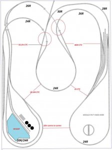
Rendering from trackplan software, railsail4-750x1001.jpg

Phil

**************************
To which I replied...

Thanks Phil for that latest rendering of my track plan. I wanted to make a few replies to it before I go off on another tangent .

Lets assume I consider the edge of the layout in these locations a minimum of 3" from the track centers (about 2.4" from the 'outer rail'). Then at my shed's entrance the CTC distance becomes 32-6=26". Lets see a lot of house interior door ways are about 29" . I think I can navigate that.

Your 2 dimensions for neck-down between the peninsula loop and the other 2 loops is 25" & 28,5". So it we subtract that same 6" from those 2, we get 19" and 22.5". OK many people find this TOOOOO restrictive. I can navigate that to slide by to get to the wider aisles at the rear. I discovered this with my cardboard mock-up (photos earlier).

BTW, it appears as though you placed the peninsula shape on the centerline of the shed. If you look at my drawing you will find that I offset that peninsula shape over to the left to provide for both a more even size aisle on either side and a more extensive freight yard on that right hand side. Even if not 'straight on the centerline', at least the head of the peninsula blob could be 'bent over' to one side or the other.

In reply to your 2 questions on grade separations,..on the one on the right I had it as 4" over 0". On the left hand one I had it as 5" over 1".

You might note that just north of those two, I specifically chose to NOT put a turnout over the lower track. Instead I placed that turnout a little further along the track so as to avoid that.
 
Last edited by a moderator:
Peco makes a 18"/22" curvered turnout, fwiw, if you want to try and go back to your original plan on the harbor. Its tight, but there are trades you have to make some times.
 
What If ??

LOTs of folks have posted messages about my narrow aisles, etc,.... so I began to think of 'what if's'.

Eliminate or Reconfigure the Peninsula

I've been thinking about a few of their suggestions about eliminating the peninsula altogether, and building a triple decker. Haven't arrived at any ideas that light my fire.


If I were to take that big peninsula out of the center of the room, it would certainly make for a more open space. And when I think about it there is not that much scenery/etc that I can fit on it compared to its size and disposition. Perhaps if I eliminated it I could make the surrounding shelves a bit bigger and fit more industry/scenery on them than I would lose by eliminating the peninsula?

One idea that entered my mind was what if I 'cut off' the root of that peninsula I had been considering, then move that circular blob down to the rear wall of the layout ? I'm going to play with idea. It might allow me to maintain the some semblance of two individual loops I had been considering, while opening up the center space.


I made this rough little sketch to explore the possibility of moving that peninsula loop/blob down against the back wall of the shed, and what that might offer in expanding the deck shelves on either side, while opening up the 'center space' of the layout. I also entertained the idea that it could be an oval loop rather than just round.

It definitely presented the possibilities of expanded decks at either side of the layout, while opening up the center space for easier movement, and perhaps an 'indoor work bench'

But I just don't know how to utilize that loop of track now,...how to enter and/or leave it, connect it in a continuous running fashion verses some sort of siding, etc.

I had thought about making it an expanded port scene rather than that previous location on the lower left, and using the lower left blob as a steel scene with my very nice 'blast furnace'.

Any new ideas??

DSCF1405, grey.jpg
 
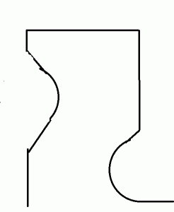
You could do something like the Tehachapi Loop in that upper "blob," especially if one side is higher than the other. One other thing you could consider: if you remove that upper blob, you could move the left or right blob up higher in respect to the other side that would allow maybe for another yard or industry...something along the lines of this Paint hack job:

TableIdea.gif
 
One Option for Oval Peninsula Loop

Here is one option I came up with today for that oval shaped peninsula loop. It would be somewhat akin to the first loop of a helix.

The track coming into it from the left side of the layout could elect to take a turnout to the right and proceed in a clockwise direction around the oval loop rise at about a 2% grade, go over a drawbridge, then split ( via turnout) to either go on up the external helix. Or it might take a right hand turnout and proceed to go down grade to the right hand side of the layout.

There will two ways a train can enter the peninsula loop, from the 'bottom' as I just described, or from the top via that track from the turntable loop or the mainline around the perimeter of the layout.

There will no longer be 2 individual loops on either side, but rather these two 'inner loops' will readily communicate with one another. And the trains on these 'inner loops' will be able to reverse their directions on the loops from a clockwise transition to counterclockwise one.

The oval peninsula loop is offset from the centerline of the shed by about 4" to the left. This could be increased so as to make the aisles on either side more equal in spacing. The sizable space allowed for the right hand side freight yard could also be cut down a few inches if needed for more aisleway, as there is already much more space for this yard due to the wider deck on that side.
maybe%20oval%20loop%20%20peninsula%20plan.jpg
 
Forget all of this talk regarding the narrow aisles. The basic layout in post #114 is not bad and the aisles are workable, even for an overweight person like me. I think that I posted earlier that I have a squeeze point of 22" that I can navigate comfortably without rubbing the fascia on either side. You need to be more concerned with the grade separations that Phil noted in that drawing. Both can be easily eliminated by doing just what I suggested over on the left side, switching the destination of the legs coming out of the turnouts, and that you did. Tunnels and bridges are something that many want to have on their layouts, but they are sometimes not practical. We have to make compromises many times. If you want a lot of bridges, design creeks and streams into the plan where clearance isn't an issue. That's what I did.

Willie
 
Forget all of this talk regarding the narrow aisles. The basic layout in post #114 is not bad and the aisles are workable, even for an overweight person like me. I think that I posted earlier that I have a squeeze point of 22" that I can navigate comfortably without rubbing the fascia on either side.
Thanks for that reinforcement

You need to be more concerned with the grade separations that Phil noted in that drawing.


Both can be easily eliminated by doing just what I suggested over on the left side, switching the destination of the legs coming out of the turnouts, and that you did. Tunnels and bridges are something that many want to have on their layouts, but they are sometimes not practical. We have to make compromises many times. If you want a lot of bridges, design creeks and streams into the plan where clearance isn't an issue. That's what I did.

Willie
I discovered a mistake I had been making when laying out those grades,...discovered it when I began looking at new condensed version of peninsula. I had been by mistake thinking of a change in grade of 1" as occurring every 24" verses 48" to get close to an approx 2% grade. So my old grades on those sketches were actually 4% rather than 2%.

BTW, I like a lot of bridges, and some tunnels.

I must admit that I like the more open space of my newest version, particularly if I have both bridges across the entrance way in place while I am running trains, and working at some sort of small workbench in the center space, rather than communicating with a workbench out the doorway.

Haven't made a definite decision yet on what version,...just wanted to explore alternatives in a 'planning stage' instead of a 'construction stage'.


Back
Top