Flange-ways in our Turnouts


beiland

Well-Known Member
While researching this subject recently, of 'excessive size flangeways' in commercially available turnouts, I was finding lots of really interesting discussions scattered about the internet and multiple railroad forums. I was running out of bookmarks to try and recall all of them. That prompted me to start this subject thread to try and bring a lot of those discussions, links and photo references into one central subject thread that I could revert back to when I failed to remember some particular posting on specific 'derailment problems' of our turnouts.

Naturally it is not just problems with the turnouts nor the wheels themselves individually. Its a 'system' of the two.

So I thought this posting was rather interesting to start the subject thread out,...
[url]http://www.ostpubs.com/systems-thinking/[/URL]

The following is an excerpt from The Missing Conversation Vol. 03, coming Jan. 1, 2013.

As John Armstrong notes in his classic book: The Railroad-What It Is, What It Does, it is futile to argue which was more important, a track system of rails, flanged wheels or the concept of coupling multiple cars together to form a train. All three taken together make up the most significant system of technology in the history of transportation to date: applying the heat energy output of a machine to transcend the capacity of animal power in moving cargo.

System_002.jpg


Wheels
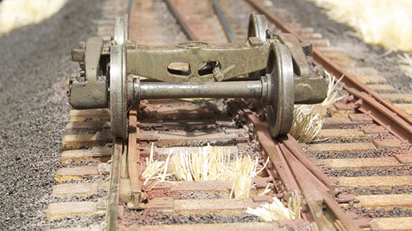
A prototype wheel looks deceptively simple at first glance, yet it is anything but. Full size train wheels have a number of functions to perform, with millions of dollars of freight and many lives riding on the outcome. Railroad wheels and track are a complex, integrated system that is carefully monitored and maintained for the safety of all concerned. As we’ll see, standards are critically important.

The beginning
The earliest railroad wheels were little more than modified wagon wheels that were sufficient to carry the lightweight railroad cars of the day. Although spoked wheel designs in both wood and metal were quite common, they soon proved unsuitable and were replaced by wheels having a disk design, typically of cast iron, which was easily worked by the metal smiths of the era. These designs evolved into the wheels we know today.

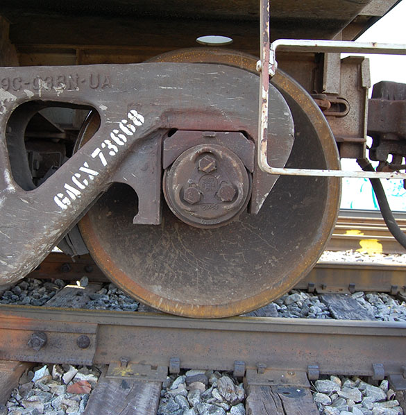
Cast iron tends toward brittleness and foundry men discovered that an extremely hard chill developed in the iron if it was poured next to another iron surface. This chilled area, as deep as an inch, could not be machined and was typically avoided. However, it proved ideal for the wear surface on freight car wheels. Therefore the rim and flange were poured as a unit against an iron ring, leaving the interior and hub areas soft and machinable.

Other considerations
You would think things like wheel diameter, tire width and flange depth appear straightforward enough, yet such was not the case initially.

Take the diameter for example. Larger wheels provided a better ride but added to the dead weight of the car. They were more expensive too, an important consideration given the ultimate number of wheels required by any line.

From what is known, a diameter of 36 inches appears to have been an early standard for freight cars. However, roads like the B&O used smaller 30 inch wheels on certain cars in the 1830s progressing in size to 31 inches, even though a compromise of diameter of 33 inches was widely accepted in America by the 1840s.

Gauging the impact of interchange
Early railroads were essentially closed systems. The trains of one line typically didn’t travel on competing lines and passengers and freight were manually transferred at end points or junctions. As rail travel and shipping of freight became more widespread, this cumbersome process began to fall apart. With manual transloading being horribly inefficient, the superiority of having cars able to travel freely from point to point soon became clear. Yet there was a huge problem looming: track gauge was anything but universal.

The interchange of freight cars among competing rail lines was unprecedented in American business history. It worked because everybody benefitted, either by increased efficiency, lower costs or both. The fly in the ointment was the wide variety of track gauges used in the United States at this time. Driven by local political interests, hubris among the “empire builders”, greediness in keeping traffic confined to their system or just an urge to be different, track gauge standards were all over the place. Pioneered by brothers George and Robert Stephenson, the Stephenson gauge of 4’ 8.5” was commonly used, accounting for over 50 percent of track miles in 1861, with the 4’10” gauge common in the states of Ohio and New Jersey only accounting for 9.9 percent. In the American South, five feet was the common standard comprising 21.9 percent of total miles of track, while the Erie Railroad’s famously broad gauge of six feet only represented a mere 5.3 percent.

Think that’s wide? A line in Missouri used 6’ 6” as their gauge for reasons no one understood. Rail lines in between these extremes used a gauge of 4’9” in an attempt to compromise the differences between the Stephenson gauge and 4’ 10”. Given the extent of trackage laid, compromise solutions to the problems of interchange abounded. Some were more laughable than others.

One stop-gap idea widely adopted for a time was an extra wide wheel tread that could traverse tracks laid to 4’-8.5” up to 4’10”. This proved to be ill-conceived at best because the running qualities of these wheels were horrible, due to the fact they didn’t conform to either gauge. By necessity the wheel flanges had to be gauged to the narrowest track leaving a lot of side-to-side slop on the wider gauges. Cars so equipped could only be moved at slow speeds and, while freight might withstand some jostling around, passengers were less tolerant. Suffice to say that railroad men hated these things.

Other schemes such as exchanging trucks, multi-gauged track composed of three and, in one case, four rails were all tried but the only solution that was going to work efficiently was to adopt a standard track gauge dimension. With miles of track already laid many lines were resistant to regauging their track, yet the handwriting was on the wall and all lines eventually adopted the Standard Gauge of 4’ 8.5”. Finally, a car could travel from one part of the country to another without the problems of delay from transloading, switching trucks and other impediments.

That's some interesting history I was unaware of, or had forgotten :cool:
 
Last edited by a moderator:
Systems Thinking

a followup by Mike....

As the excerpt from TMC 03 conveys, track and wheels are an integrated system: in essence, two sides of the same coin and this relationship is just as true for our models as for the prototype. One cannot alter one part of the equation without impacting the other.

System_000.jpg


The P48 wheels and track shown above, illustrate this interdependent relationship of how the frog and guardrails work in combination with the wheel profile to guide the truck safely through the turnout. Notice in particular how the wheel is completely supported by the frog as it bridges the gap of the flangeway.This is just as critical in model form as it is on the prototype. The system is made of the width of the tire, the depth and thickness of the flange; the shape of the fillet where the flange transitions into the tire and the back-to-back distance between the inside faces of the wheels. These are complimented by the track components such as the shape of the rail head, which matches the shape of the tire, the width of the flangeways at the frog and guardrails, plus the back-to-back distance between these two.

A solution often promoted in O scale is to finally adjust the track gauge to proper dimensions but keep the existing coarse standards for wheels and flangeways. The thinking presumably is that this will allow all the existing legacy equipment built to five foot gauge to still have a place (just swap out the trucks and some drive wheels). Further claims are that it also allows modelers to decide for themselves whether to keep the legacy standards or adopt P48 for the sake of consistency.

Here’s why I think this is a bad idea: A compromise is a compromise is a compromise. This is the situation in HO now. HO has one track gauge yet it also has multiple options for wheel specs such as the RP25, Code 88 semi-scale and P87 proto-scale.

System_001.jpg


Look closely at this image of P87 wheels on a regular HO scale Shinohara turnout. There are a multitude of problems here. Even though the track gauge is acceptable for P87, the flangeways are not. While the grossly oversized flangeways work with the out-of-scale NMRA wheels they were designed for, the P87 wheels have nothing to support or guide them through the frog. Notice the huge gap between the wheel face and guardrail on the left. Why is it so huge? Because the back-to-back dimension is vastly different between P87 and the NMRA standard. By reducing the width of the wheel tread and thickness of the flange to scale dimensions, the back-to-back distance is also widened. Do you see how interdependent all these relationships are and why changing just one aspect affects all the others?

Notice further how the wheel on the frog has fallen into the gap created by the wide flangeway, instead of being supported by the wing rail as it should be. The semi-scale Code 88 wheels that are becoming more popular in HO are not designed to this flangeway either. While they don’t drop into the gap completely, there is a noticeable bump when traversing certain brands of turnouts. Like the compromise attempt of the extra wide tires used by the prototype, such compromised solutions on our models are only marginally effective. Our models, like the prototype are made up of systems. It’s all or nothing, pick your standards and be consistent.

Why
Why does this matter to us as modelers? I believe that fine scale modeling is the visible outcome of a journey that starts with the prototype. A modeler starts with a closer examination of the prototype and, as a result, gains a more thorough knowledge of the components and how they work together. With that knowledge comes greater clarity of how compromised many aspects of our models have become over time. From that point I believe a decision has to be made: Accept the out-of-scale features for the compromise they are or continue the journey wherever it leads.

I understand that many folks are happy with such compromises for the simplicity of building with readily available products or the savings in time they offer. For my modeling such visual discrepancies ruin the effect I want to achieve. For me, such details matter a great deal. I believe it’s important that a model be consistent in scale from the rails to the running board, which is why I choose to follow the path wherever it leads.

Regards,
Mike
 
Last edited by a moderator:
I understand that many folks are happy with such compromises for the simplicity of building with readily available products or the savings in time they offer. For my modeling such visual discrepancies ruin the effect I want to achieve. For me, such details matter a great deal. I believe it’s important that a model be consistent in scale from the rails to the running board, which is why I choose to follow the path wherever it leads.

I first noticed the "problem" when using KATO code 83 Uni-track, maybe five years ago. even BB era box cars with sprung trucks were doing a "dance" over a #6 frog. I build in Code 70, primarily because I like the overall appearance. I use mostly Micro Engineering #6 switches throughout the layout. While there is no real pattern, just about every movement has frog hopper, and as long as nothing picks a switch or climbs a frog, I'm good. Operating over the Penn Central warps my perception of track work, even in HO Scale.

Seriously, short of building our own switches, there is no alternative other than to use what we have to work with. We can close the flangeways on the guard rail, but that will create problems with RP25 wheels. Frankly, my biggest derailment problem on switches, is caused by points that open up under movement. usually, that is because of some unseen pressure point causing the point to spring out of place. I agree, no one wins when we compromise, and much depends on what level of operating you are looking for. I lack the patience and vision to build to fine scale standards, which Is why I tend to avoid Code 88, and Proto 87 wheels. I have to accept my limitations also. However, I do understand your point, and at least partially agree.

Boris
 
This is an interesting post. I have seen a number of people remarking about having problems with the flangeways in frog. I guess that I am lucky because I have never experienced and problems at all with them. My track is all code 70, either hand laid or Shinohara. All the wheels on my freight equipment have metal wheels from either Kadee, Intermountain or Proto 2000 and cars all run smoothly through any of my turnouts, hand laid or the Shinohara.

In this video, the frog is in about the center of the screen and there is little or no movement of the cars as they pass over the frog.

[video=youtube;3p6VEsjM1tc]https://www.youtube.com/watch?v=3p6VEsjM1tc&index=12&list=UUpe539gp80GddF8 4WMrSNzw[/video]
 
Mechanical aspects vs Electrical aspects

If we momentarily disregard the electrical aspects (shorting, DCC friendly or not, etc), then primarily we need to look at the depth of the flangeways (particularly at the frog point), and the width of the flangeways (both at the frog point, and the guide/safety rails).

DEPTH of Flangeway:
Most of us know that the European trains, and some of our early American ones had rather big flanges on their wheels. The commercial turnout builders had to provide rather deep flangeways to accommodate these larger flanges. Many European makers still continue to provide such designs to accommodate their clients. USA makers have been modifying their turnouts to adjust to the wide acceptance of much smaller wheel flanges, and increased us of smaller code rail.

Thus we Americans now see a significant decrease in flangeway depths at the frog. Some have even argued for such shallow flangeway depths as to allow the wheel flanges to roll UPON them for the short distances in the area of 'just prior' to the frogs points. This might seem like a good idea at first (some even suggesting shimming up this 'valley' in older turnouts to prevent the wheel from dropping into this 'cravice'), but there are dangers here also.

BTW there is another subject thread on this forum that has some members running experiments and measurements with this subject of flangeway depth / wheel flange size,...

Bone-headed move to RP25

...and on page 7
I took 16 readings off of various manufactured wheel sets and found the flange depths to be consistently around .025 deep. Variation ran from .024 to .030, however, the .030 reading was taken from a Varney Docksider (Little Joe) which is possibly older than 60 years. So RP-25 is older than July of 2009, the latest revision.

Making a pad for the bottom of the frog flange-way that is .020 thick, per how Willie is doing it would seem the correct way to fix the dip into the frog that cars and locomotives do. My guess is that Atlas made this depth to handle the older cars and locomotives which had the old Pizza Cutter Flanges and never corrected the frog to fit the new standards. Nobody complained, so the squeaky wheel never got greased!


WIDTH of Flangeways:
Here we two areas of consideration, 1) the width of the flangeways at the outer tracks, and 2) the width of the flangeways at the inner areas next to the frog point (often referred to the 'wing rails). Both of these areas are very important to help our train wheels/trucks get thru our turnouts in the best manner. In both cases it is general most desirable that these 'sometimes broad width' flangeways be restricted in width as much as possible WITHOUT undue restriction to the smooth passage of the wheel flange thru the turnout.

Please remember here that we DO NOT want to look at this situation while considering just a single axle passing thru, but rather a 'truck' of axles that is likely 2 or 3 axles strung together, and likely in a 'rigid form'.

...some illustrations
Wheel Bridging Frog.jpg

Flangeway guides-rails, shimming.jpg
....this guideway shimming is often suggested for Peco turouts
 
Last edited by a moderator:
Just FYI I have mostly Peco Code 83 Streamline turnouts (#5, #6 and #7 "curved") and I have no problems with them at all.

Frederick
 
I just don't seem to have all these problems. I have my own hand-laid turnouts of various kinds, Peco Streamline Code 83 #6's in large numbers, and some Walthers/Shinohara curved turnouts that are Code 83 and have either #7.5 or #8 frogs. I have had some shorts with steamers at the frogs of the curved turnouts, which I took care of by cutting a second gap about 0.25" further out than their plastic spacer. For example, the BLI T1 Duplex is not articulated. It resembles the prototype in all details except that the two center driver axles are blind...no flanges. On the #7.5 turnouts, when the blind drivers' tires cross over the frogs, they want to drift inward along the curve and in doing so they make momentary contact with the wrong frog rail. But I've' not had problems picking frog points on any of my turnouts, and I have a wide array of rolling stock.
 
It does appear that Code 83 users have less problems, as these came along after the Code 100 rail products, and since most were targeted at the American market, there were adjustments made in the design of them.

Are there many (any) European track/turnout manufactures supplying Code 83 stuff (other than Peco).

Tillig makes some nice products in Code 83. The turnouts, for example, don't use "hinges" of any sort for the point rails. It seems they are manufactured to NEM standards but I don't know what they are.

They are a bit pricey.

Frederick
 
I'm lucky or blessed, laid scale miles of code 100 track with 24 turnouts in the mix and ran everything at max warp. No worries, I could go up and get coffee and if a switch did not trip I was good to go. Ran em for hours. Absolutely EXCELLENT thread, most informative AND helpful! Thanks for posting.
 
As I posted on another thread, I have 110+ Atlas turnouts on my layout all code 100. The main issue is the wheels dropping slightly but not derailing at the frog. To fix this, I insert a "V" shaped piece of .015" or .020" piece of styrene into the recess. The flange then rides on the insert instead of dropping. As I pointed out, the dropping doesn't cause issues but looks un-prototypical. This only affects #6 or larger turnouts.

Willie
 
Inserts for Flange Depths

As I posted on another thread, I have 110+ Atlas turnouts on my layout all code 100. The main issue is the wheels dropping slightly but not derailing at the frog. To fix this, I insert a "V" shaped piece of .015" or .020" piece of styrene into the recess. The flange then rides on the insert instead of dropping. As I pointed out, the dropping doesn't cause issues but looks un-prototypical. This only affects #6 or larger turnouts.

Willie
Yes it is those larger/broader turnouts (dble curved and single curved) that end up with those longer 'unsupprted by railhead' situations just prior to the frog points. Yet it is often proselytized that we should seek out larger sweeping radius turns and turnouts, where we are more likely to find problems with the flangways, particularly with thinner 'scale wheels'.

One other item I ran into when reading about these subjects was the suggestion that these 'valley bottoms' be shimmed up with metal V pieces. I just can't imagine a metal RR wheel's flange riding across one of these metal shims, in close proximity as opposed to very direct firm contact while, utilizing DCC. I would think there would be multiple arcing possibilities between the wheel flange and the metal shim?
 
NMRA Bone-headed move to RP25

BTW, this was a subject thread I ran across on this forum while I was first looking for discussions of flangeways in our turnouts,....

Well, I just got off the phone with a manufacturer and found out why my new engines and cars derail all the time.

According to the manufacturer, the problem is the RP25 wheel standard by NMRA. They said they get returns all the time now because the RP25 standard has the wheel flanges too shallow.

The manufacturer told me they warned NMRA about this, and NMRA went ahead and changed to the RP25 anyway.

My choice is to rip out all my code 100 track and go to a code 83, and to pay particular attention to the types of turnouts I buy, or just not buy newer rolling stock and engines. The fellow on the phone said the new RP25 stuff is a headache no matter how careful the layout when it is code 100 rail.

What a bone-headed move by NMRA. I'll have a garage sale and go find something else to do before I spend hours on end machining my own wheels. What the heck were they thinking?

So now I know. With code 100 track and Atlas turnouts, I'm just shafted for ever buying something new if the wheels are made to NMRA RP25 standards. At least that is what the manufacturer says, and that is what my own measurements and test on my track also show.

In a small market like this, a bone-headed move like RP25 is a big problem. I wonder how many people were working like crazy to fix problems caused by new wheels?

Where can I buy old wheels with taller flanges in a 1 inch axle width?? Anyone know??

Tom


...and then a good reply...
Tom;

Very interesting that a manufacturer would complain about RP-25 flanges now, esp. since that RP has been in place since the early 1960's, if not before then. I remember seeing ads from that time for Lindberg Trucks, stating that they now come with the RP-25 wheels.

He's gotta be blowing air up your skirt. I use code 83 and code 70 rail now, and in the past even had some code 40 rail on a couple of earlier layouts. Even on that very small rail, I have no problem with derailments, AT ALL! 99.9% of my cars and all of my locos have RP-25 flanges.

In fact, except for older used equipment, or some European made equipment made to the older NEM standards, it's almost impossible to buy anything with RP-25 wheels or its equivalent.

It was proven many years ago, that its not the flange depth that determines trackability. Its the fillet between the flange and the wheel, and the quality of the trackwork.

To make a long story even longer, its your trackwork, and not your flanges.
 
Tillig makes some nice products in Code 83. The turnouts, for example, don't use "hinges" of any sort for the point rails. It seems they are manufactured to NEM standards but I don't know what they are.

They are a bit pricey.

Frederick

We had a dealer here a few years back, who showed their wares at our train show, I was very impressed with the quality. The club used the dual 12mm/16.5mm track on part of the layout, when trying to encourage some HO participation of QR profile trains. Unfortunately it never took off and was mostly removed not long before RTR models started to become available. Some 12mm track of theirs has been added to another donated layout. Tillig also, I believe was one of the first to make curved turnouts available and later made turnouts that had a certain amount of flexibility to overcome alignment anomalies. The main visual difference was, in keeping with continental practice, was the use of angle iron (simulated plastic) check rails, that were not compliant with the usual rail sections, prototypically used in the US and here. They were pricey, but the use of the non-hinged point rails, like the Fast Tracks hand laid ones made for reliability and a nice appearance.

Peco Streamline is the most popular here.
 
One of the things I noticed about the video from Fast Track is that they show the wheels as being the same diameter across their width, which is not how the wheels are made. Railroad wheels, full scale; or, model are tapered, the diameter getting smaller the farther away from the flange you measure. I also found that the flange can be from .024 to .030 in height. This was measured on my own wheels here on my layout and was found to vary slightly with the flanges from the same manufacturer. Like Chet, I use a few different manufacturers wheels with LLP2K wheels the majority, Some Kadee and others, as I experiment with trying to find a good replacement for the Life Like and older Walthers wheel sets.

We all seem to have different, "Givens and Druthers", as far as the track we work with. I would say that Atlas track I've used probably has the the largest tolerances. The point on frog is pretty dull and the gap between the point of the frog and the guide rails is maybe to large. The changes in Atlas track that I would like to see, would of course make the track more expensive and I went with Atlas because of the savings it offered.

This is a great thread! Thanks for starting it Beiland! Now, can we get away from the NMRA's Standard RP-25 being bone headed?

The one thing I can tell you is I'm not about to tear out my Atlas Code 100 track to fix any problems with it! However, I may modify it to make it better. That should be the focus here, how to make our track better. To truly understand what is going on, the modeler needs to invest in a caliper. Digital Calipers are very reasonably priced now-a-days and very versatile uyou can switch between standard and metric, with the push of a button. You can also zero of any measurement you want
 
Last edited by a moderator:
Wheel Taper & Calipers

One of the things I noticed about the video from Fast Track is that they show the wheels as being the same diameter across their width, which is not how the wheels are made. Railroad wheels, full scale; or, model are tapered, the diameter getting smaller the farther away from the flange you measure. I also found that the flange can be from .024 to .030 in height. This was measured on my own wheels here on my layout and was found to vary slightly with the flanges from the same manufacturer. Like Chet, I use a few different manufacturers wheels with LLP2K wheels the majority, Some Kadee and others, as I experiment with trying to find a good replacement for the Life Like and older Walthers wheel sets.
I did take notice of your measuring experiments, and appreciate them.

I'm not so sure that most of our 'model size' wheels have same 'tapers' that the real ones do?


The one thing I can tell you is I'm not about to tear out my Atlas Code 100 track to fix any problems with it! However, I may modify it to make it better. That should be the focus here, how to make our track better. To truly understand what is going on, the modeler needs to invest in a caliper. Digital Calipers are very reasonably priced now-a-days and very versatile uyou can switch between standard and metric, with the push of a button. You can also zero of any measurement you want
I need to get out my calipers and play with them a bit more as well.
 
Trucks of Multiple Wheel Sets

Another consideration we need to make about turnout problems is NOT only the passage of a single axle wheel set thru them, but rather the passage of a 'truck' full of wheel axles thru them.

For instance just a 2 axle, 4 wheel truck going thru our turnout, the most common found on our freight cars. Generally we have two types of trucks in terms of 'flexibility',....what we might term as relatively rigid, verses flexible. The flexible ones are those that allow the 2 side-frames to move (twist) independently quite readily, while the most common ones are somewhat rigid in nature.

I've found the use of the 'rigid trucks' to be easier to work with, particularly not needing to be flexible over such a short distance as between the 2 axles/wheels of the truck. This rigidity helps the truck negotiate the valley gaps in a turnout, even excessive deep ones without as much dipping of the freight car itself.

We just need to remember to attach these 'rigid trucks' to our freight cars in the proper manner, one end pretty firm, and the other loose enough to allow the car to rock sideways.

There must be some sort of video(s) covering this subject??


Back
Top