Drop feeders


new guy

Active Member
I'm still running multiple (6, sometimes 9 locos/w/lights and sound!) trains on 400+ feet of track with ONE (1) power feed. I notice no 'slow spots' and everybody trucks along with no trouble. Half the track is new out of the box and half was OLD and had SCHMUTS on the rails with old joins that were 'welded' on with corrosion. I chucked the old joins and hit the top and inside edge with 320 sandpaper and a file on the ends where the joins touch the rail and NO PROBLEMS!

So what is the deal? I had everybody telling me 'drops every three feet' and I was curious about just HOW much I can push this and I have pushed it pretty far with NO trouble.

I'm all DCC using an NCE 5 amp system and nothing else, the feed is at one end and not centrally located.

Is the 'every three feet rule' a hold over from low amp DC systems? I was ready to bust this into three blocks but I don't see a need now.


I'll add another few hundred feet of track and see.
 
I may be wrong but I don't think you would need feeders every 3 feet. You do have weak spots so I would make sure they are covered with extra feeders. Don't need to worry about blocking unless you curve back on the same track and have your polarized reverse on you. You might think on adding a second power pack have each power pack run 200 ft. The 3ft is a resistance thing your power will drop in the rail from resistance. A 10ft lead may not need 3 ft between Leeds while a 20 ft may. Plus it also determand by your track better track less resistance. That's my take on it if I understand my limited electrical schooling and what I picked up here.
 
First of all, kudos to you on your trackwork if you can get 400+ feet to operate on one set of power feeders. 6-9 locos will not draw enough power to overheat the feeders that I think you are using. You are getting voltage drops whether you notice or not...is it any more than you would get by running an additional set of wires 45'? Probably not. To me drops every three feet is overkill. Where I use flextrack, I have feeders at every other joint, meaning every piece or track is connected. It is insurance for me as it is easier to deal with it when constructing the layout than it is to add after ballasting and scenery are in place. Access later can also be a problem. Leaning over scenery to solder wires may not be too easy on some layouts. Over time dust, humidity and airborne pollutants will have an effect on the track and joiners, hence the stuff you saw on the used track you had. When? It all depends on the conditions of the area where the layout is located. Expansion/contraction of track can also be a minor problem to some. You may never see any problems.
Is the 'every three feet rule' a hold over from low amp DC systems?
Actually DC systems are usually a little more tolerant than DCC when it comes to power feeders.
I was ready to bust this into three blocks but I don't see a need now.
I think blocks on DCC layouts are more for isolating troubleshooting, and for something called "power districts". Since I don't use DCC, I am no expert by any means.
Keep adding. If it works, great! If not, this is still a temporary layout if I remember correctly.
Willie
 
Having feeders every 3' or for each section of flex track is a safety measure and little else. You are correct, it is not needed and (as Willie said) having feeders every 3' is over kill. I think I can safely say the main reason for this is to ensure a stable power supply to the track as, in time, joins will deteriorate resulting in a loss of power from one section of track to the next resulting in engines coming to a grinding halt due to no power, or insufficient power, to run them. It is much easier to put in more feeders than maybe needed from the start than trying to add them at a later time.

With that being said though, I am impressed that you can run 6 - 9 DCC engines (with lights and sound) on 400+' of track with just one power source, especially with the NCE 5 amp system. If memory serves me correctly I think NCE even says that 5 engines is the recommended.

Thanks, I'm no genius or anything special THATS for sure, kinda surprised I've been so successful so far. I guess there is an advantage to NOT knowing the 'limits' of what you are doing sometimes.

Age and strength of connection between pieces then, seems to be the key here, over time I'm certain this would deteriorate substantially. The 'high line' is secured to blocks but the blocks are not secured and running trains over time the track "walks" the blocks into the other lines! It IS 'temporary' after all, just an experiment with a new toy at this stage. I most certainly do not 'poo-poo' the idea of many feeds to a PERMANENT layout! I'm thinking that I may not need em every three feet though, I'm now planning on soldering many of the joins on the 'permanent' track and dropping down between them with expansion gaps at the wired joins every 6-10 feet. Should cut down on the clutter underneath the table and save on wire, copper is pricey!

Thanks again guys, you're the best!
 
So what is the deal? I had everybody telling me 'drops every three feet' and I was curious about just HOW much I can push this and I have pushed it pretty far with NO trouble.
I've not measured but I regularly run large sets with a single feeder with no issues. For example every loop in the Christmas Forest this year had a single feeder even on the stainless steel track, and that is G-gauge. My biggest issue was having the locos stall on the plastic frogs on the crossings which has nothing to do with the power supply. One of my very largest Christmas Forest layouts from way back 1994 or so, the entire layout was run on 2 bell wire feeders. I believe we ran 4-5 trains G-gauge on that same track. I do have to say that it WAS brass track which is an excellent conductor, but once again zero issues.

I do not understand why others have so many issues. Seems some other people have huge issues and need to run multiple feeders on tiny layouts even 4x8 type. I have almost every brand of DCC system (Lenz, MRC, Digitrax, CVP, and NEC) and don't have issues with any of them.

I presume you used the sand paper to clean the joints not the top of the rail. I have had issues with that. Not that it doesn't work great, but more that the track surface is scratched up such that it gets dirtier much quicker, and needs to be "hit" repeatedly.
 
Last edited by a moderator:
I'm still running multiple trains on 400+ feet of track with ONE (1) power feed.
I presume this is a loop. Even if it is only a single loop any given train would be at most 200 feet from the feeder, a double loop it would only be 100 feet, and a triple loop 66'. That is the true measure, max distance from feeder to loco. That is another thing I've not understood about how people calculate feeders. If one puts a feeder every 3 feet the train is never more than 1.5 feet away from power. People who propose 3' feeders are telling me that a nickel silver rail cannot effectively conduct power for more 2 feet?!? 10 foot feeders for 5 feet from a feeder seems much more reasonable to me. Our modular layout has a feeder every 4 feet, but that is because each module has 1 feeder and they are only 4' long. My philosophy isn't that I need feeders to get power to the rails but I have feeders to make up for poor rail joiners as the bus will skirt around any bad joiners. Of course even then I seldom have bad joiners because I always use only new joiners on permanent track. The Christmas Forest joiners are going to need some looking at soon as some of them have been put together and taken apart 40 times or so - Yipes.

I think the "deal" is that someone somewhere had issues, so everyone else assumes they are going to have the same issues. I am constantly telling folks, "Don't invent problems that don't exist.", and "Don't make things harder than they have to be.". Put two wires to the rail and if an issue occurs then add the necessary to fix that exact issue. Most people's layouts are not complex enough, nor large enough, nor permanent enough to dictate they be made atomic bomb and idiot proof from the get go.

One other thing to consider is short circuit protection. Just because the trains are running ok doesn't mean the system is. If a short circuit occurs at the farthest point away from the feeder, does the circuit breaker in the unit trip? If not you need more feeders. Such a short can fry not only the command station but cause damage to the units causing the short circuit. This is why you have probably heard about the quarter test. If a quarter across the rails doesn't trip the circuit breaker it needs more feeders.
 
Last edited by a moderator:
5 loops, one of them 'elevated', and a figure 8 inside em bigger than the smallest loop.
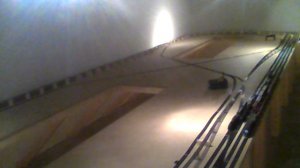
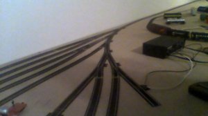
WIN_20160107_142049.JPGThe feed is behind me to the right.
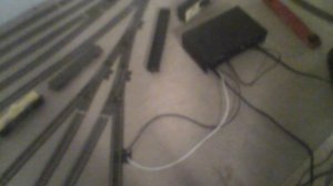
WIN_20160107_142335.JPG18 gage wire to a normal terminal piece. All new joins and the 'old track' is mostly brass between the new nickel/silver, some of the set 18" curves are foreign and I don't have a clue as to what they are made of, I hit the top of the rail and the inside edge where the wheel flange rubs just till I can see 'fresh metal' and the ends where they butt up and on to the next piece. I have a track 'issue' at almost the farthest point from the feed where an expansion gap got BIG from the sliding rail of the flex "walking" towards the corner and occasional derailments there have caused the system to stop properly. The "moving rails syndrome" of the 'slider' in the flex was an unforeseen but not insurmountable problem. Solder.
 
the 'old track' is mostly brass
Brass is far and away a better conductor of electricity than nickel-silver. All the "wiring for DCC" stuff one sees generally assumes nickel-silver rail, and the extra bus wire and feeds is compensating for it.
 
All I can say is.... HOW IN THE HECK??? What switches are you using? What about the diverging tracks having power?

You need power feeders in all three sides of each and every single switch. Or you simply cannot run the locomotives and have power to them, on each diverging track.

Of course unless you are only running on the mainline on only one track, and whats the point in that, if you have no power to your locos on all the other yard tracks, sidings, etc.
 
Last edited by a moderator:
Michael - I have to disagree with you. I have turnouts all over my layout without power feeders on the diverging routes. I use Atlas Custom Line switches with insulated frogs with no additional wiring. As long as you don't have an insulated rail joiner in the mix somewhere, you don't need additional feeders. I believe most other brands are the same.
Willie
 
Engineering fact is if you have a longer run through nickel silver track you will have a larger voltage drop. Depending on how you operate your layout may determine how important that is.

Every rail joint is an opportunity for a bad connection. The voltage can drop or even lose contact altogether. If there are humid conditions or the track is painted or some other contaminent gets into the joint, it can fail electrically. It happens.

It you only have one feeder and it works to your satisfaction, great. There still are the risks of a joint going bad.

I handlay my track and use insulated frogs and throwbars in my switches. That means I end up with a lot of feeders. If you are using commercial track then those feeders are built into the switch.

The concept of a feeder every three feet is really saying every piece of rail gets its own feeder (since flex track is 3 feet long and stick rail is sold in 3 ft long pieces). If you are putting feeders "every three feet" what you are doing is saying that you are not relying on any rail joiners to conduct electricity. Every rail has a soldered connection to the power source. That arrangement guarantees the lowest possible voltage drop and the cleanest signal between the control system and the engine. Is it overkill? Maybe. It depends on how much time you want to spend ensuring reliability. Some people want things "bulletproof". Eventually a layout with one set of feeders will develop a problem, metal corrodes. A layout with many feeders is less likely to suffer those problems. A layout with feeders every three feet will never suffer a rail joiner contact failure because the rail joiners aren't critical to the electrical path.
 
All I can say is.... HOW IN THE HECK??? What switches are you using? What about the diverging tracks having power?

You need power feeders in all three sides of each and every single switch. Or you simply cannot run the locomotives and have power to them, on each diverging track.

Of course unless you are only running on the mainline on only one track, and whats the point in that, if you have no power to your locos on all the other yard tracks, sidings, etc.

All I can say is I DON'T KNOW! Atlas switches mostly.
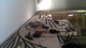
WIN_20160108_081152.JPGThere is the 1 hook up at the bottom of the pic, the black and white wires to a normal terminal piece.
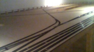
WIN_20160102_075216.JPGIt's all 'hot track'! I can run loco's on every inch!
 
You need power feeders in all three sides of each and every single switch. Or you simply cannot run the locomotives and have power to them, on each diverging track.
Where in the world did you get that idea? That statement is marginally true only if one is using power routing turnouts. Even in that case, one only "needs" 1/2 a feed on the frog side if it is not in a loop, and only if one wants to run a train on that dead-end spur when the turnout is thrown against it.
 
Last edited by a moderator:
I use Peco insulated code 83 switches. If I only have a power feeder in the leading track, when I throw the switch it only powers either the straight through track, or the diverging track, but not both.
 
I use Peco insulated code 83 switches. If I only have a power feeder in the leading track, when I throw the switch it only powers either the straight through track, or the diverging track, but not both.
Yes, that is what I figured, but what I meant is where did you get the idea that, this behavior applies to other turnouts? I thought I had seen you through the last few years participating in many other discussions (both here and on the other side of the tracks) on this topic. :confused: I must be thinking of someone else.

I will guess that about 90% of the turnouts out there, (especially old brass ones from AHM, Tyco, Atlas, Bachmann, Lifelike, Marx, Mantua, etc.etc.etc.), do not work that way.
 
Last edited by a moderator:
new guy, out of curiosity, what is the approximate length of the longest circuit of track on your layout, that could ever be powered at any given time (outer loop perhaps, but not necessarily)?

-Rich
 
new guy, out of curiosity, what is the approximate length of the longest circuit of track on your layout, that could ever be powered at any given time (outer loop perhaps, but not necessarily)?

-Rich

Good question so I got the tape and checked, from here at the terminal piece, 10 feet to the loops
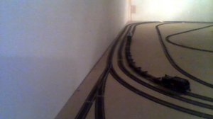
WIN_20160126_120415.JPGIt goes down to a single line at the top of the pic
single line to here, 20 feet to the wall 30 feet to the left it comes back the same distance.
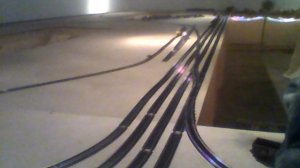
WIN_20160126_120504.JPGThat is the 'choke' point, from there the four loops and the figure 8 run the length of the table, the outside line is 100 feet of track with the others inside it. There were 5 lines, one was elevated but has come down for phase #2 construction
WIN_20160126_120533.JPGThe line going down right out of frame is the LITTLE loop that re enters at the bottom right in the second pic. The ladder is only about 6 feet from the choke point 'splitting' all the loops in half and going directly to the figure 8.

The farthest A loco can be from the transformer is only about 60 feet the way the track is laid at this time.

Got confident in my track quality and was running everyone that was "healthy" (9 loco's/w lights and sound ON) at MAX speed and finally noticed a very slight slowdown in 1 or 2 spots, CLOSE to the choke point but nothing to keep me from doing what I'm doing. Kinda glad I found a 'limit'!

Hope that helps, if I was not clear please ask away, I got no secrets and would love it if someone duplicated my "experiment" !
 
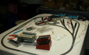
This is my experimental setup. Not sure of the size, but the table is maybe 3-1/2' x 5-1/2'. The only power feeds I have are at the lower right and via the turntable. The turnouts are all Kato power-feeding. Depending on how the switches are thrown, the mainline feeds everything up to the turntable, or the turntable can feed the entire main line. The only problems are related to specific locos.

uploadfromtaptalk1453833332292.jpg

Oh crap!
 
Last edited by a moderator:
Thanks, new guy. I was just asking to help me develop a frame of reference, as I consider designs for my first layout. You've got 400' of track, but it didn't sound like voltage was being applied to all of it at once (only what you were switching through), so I was just trying to get an upper limit in my head on what can be done reliably. As far as the longest, continuous circuit a train could travel on your layout goes (if you throttled it up and just let it run), would 250' or so sound about right?


Back
Top