
Cryogenic Plant & Helium Plant
Finished the track plans, and the base plate onto which the coal mine will be built. Now I need to turn my attention to the left and down that long ramp that will take the trains down along that side of the layout to connect back to the mainline. At the bottom of that ramp there will be an intersection of turnouts that will allow the trains to access the refinery area. The refinery area is going to fill that opposite corner, and include both oil products and propane products,....so oil and propane tank cars will be loading and moving around on these tracks on either side of the refinery.
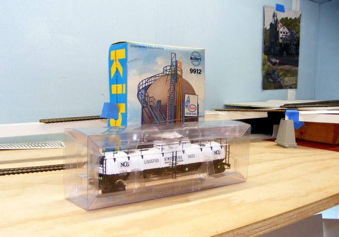
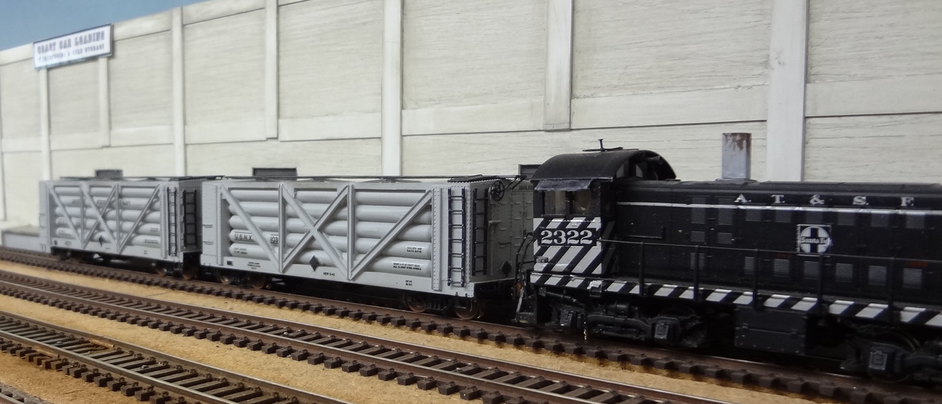
Early on I had wanted to possible find a location for at least a small cryogenic plant along with a spherical storage tank for those liquefied gases. It stems from my long time fascination with those cryogenic tank cars. I bought at least 8 of them when BLI finally bought out those plastic ones. Up to that time I figured the only way I would be able to afford those brass cars was to kit bash them like Bobby Pitts did such an excellent job on.
...one of Bobby's cars..

Lets see, can I fit something in that space between to two opposite ends of the layout, and outboard of that ramp of track? First off I needed a long track parallel to the ramp track that could allow for staging some of those tank cars that would be coming and going from the refinery. Perhaps I should have two such 'staging tracks' for the variety of tank cars involved, plus even some coal loaded cars might pay a visit.
By happenstance I placed some turnouts and spur tracks at angles off of one of those staging tracks. Here is what that looked like.
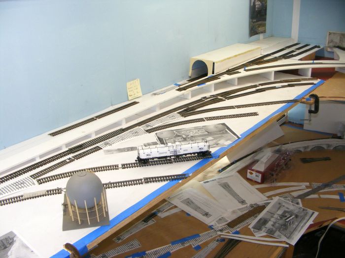

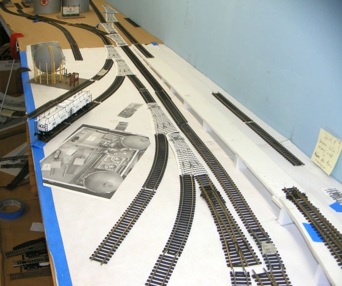

I randomly placed those spurs in 'pairs' thinking each pair could service a small plant each. And the spurs are long enough to accommodate two of those cryogenic cars. The small plants would be located in between those spurs, and might consist of spherical stowage tanks (have two already), short squat condensing towers, taller towers, etc.
Nothing set in stone,..just brainstorming.
I'm open to ideas,..suggestions?
Finished the track plans, and the base plate onto which the coal mine will be built. Now I need to turn my attention to the left and down that long ramp that will take the trains down along that side of the layout to connect back to the mainline. At the bottom of that ramp there will be an intersection of turnouts that will allow the trains to access the refinery area. The refinery area is going to fill that opposite corner, and include both oil products and propane products,....so oil and propane tank cars will be loading and moving around on these tracks on either side of the refinery.
Early on I had wanted to possible find a location for at least a small cryogenic plant along with a spherical storage tank for those liquefied gases. It stems from my long time fascination with those cryogenic tank cars. I bought at least 8 of them when BLI finally bought out those plastic ones. Up to that time I figured the only way I would be able to afford those brass cars was to kit bash them like Bobby Pitts did such an excellent job on.
...one of Bobby's cars..
Lets see, can I fit something in that space between to two opposite ends of the layout, and outboard of that ramp of track? First off I needed a long track parallel to the ramp track that could allow for staging some of those tank cars that would be coming and going from the refinery. Perhaps I should have two such 'staging tracks' for the variety of tank cars involved, plus even some coal loaded cars might pay a visit.
By happenstance I placed some turnouts and spur tracks at angles off of one of those staging tracks. Here is what that looked like.
I randomly placed those spurs in 'pairs' thinking each pair could service a small plant each. And the spurs are long enough to accommodate two of those cryogenic cars. The small plants would be located in between those spurs, and might consist of spherical stowage tanks (have two already), short squat condensing towers, taller towers, etc.
Nothing set in stone,..just brainstorming.
I'm open to ideas,..suggestions?


![[DSCF4696]](https://i.ibb.co/pP3k5wk/DSCF4696.jpg "[DSCF4696]")


![[img]](https://d28lcup14p4e72.cloudfront.net/259338/7326425/img.png "[img]")
![[Box%2520Factory%25201]](https://ogrforum.ogaugerr.com/fileSendAction/fcType/0/fcOid/89421197222447691/filePointer/91250870597249609/fodoid/91250870597249586/imageType/MEDIUM/inlineImage/true/Box%2520Factory%25201.JPG "[Box%2520Factory%25201]")
![[Box%2520Factory%25202]](https://ogrforum.ogaugerr.com/fileSendAction/fcType/0/fcOid/89421197222447691/filePointer/91250870597249610/fodoid/91250870597249587/imageType/MEDIUM/inlineImage/true/Box%2520Factory%25202.JPG "[Box%2520Factory%25202]")
![[sfcu2007211]](http://www.matts-place.com/intermodal/part2/images/tanks/sfcu2007211.jpg "[sfcu2007211]")
![[35034446102_2e00c7535c_4k]](/forum/proxy.php?image=https%3A%2F%2Flive.staticflickr.com%2F4234%2F35034446102_2e00c7535c_4k.jpg&hash=b82bc429630a32163948ed6676da5e9b "[35034446102_2e00c7535c_4k]")
![[35034437692_155a9cf1a2_4k]](/forum/proxy.php?image=https%3A%2F%2Flive.staticflickr.com%2F4212%2F35034437692_155a9cf1a2_4k.jpg&hash=381ea474f434c33e5383d205f1e04397 "[35034437692_155a9cf1a2_4k]")


