Blocking track for DCC installation


Good evening

I have a quick question regarding blocking track sections for DCC. Whilst I do understand the concept of having a main bus line as your main power then installing feeders to each block, but does each block powered by feeder's require an individual on off switch to each block same as a dc layout? I hope that makes sense!
 
It's not required, but can be very useful. If, for example, you have an engine facility with 60 locomotives, you would want to be able to turn power off to those tracks. Otherwise, the DCC system will be trying to power all those decoders. They do draw a little power, even in standby mode. Also, if you happen to encounter a short circuit, it is a lot easier to isolate the problem area.
 
Thank you for the reply, I think the total number of Locos I will be running will be no more than 3 to 4 maximum. Would you still recommend switches in that scenario? Also, is DCC prone to problems?
 
Even on a small layout, it helps to be able to switch blocks off and on to isolate potential problems as Terry posted.
Also, is DCC prone to problems?
That depends. I am posting as a DC operator and have not experienced using DCC itself. I read about a lot of problems here on the forum, but it may all just be relevant. No one posts about non-problems and that may outnumber problems to a great magnitude. It would seem to me that there should be no problems if everything is installed carefully and correctly.
 
Even on a small layout, it helps to be able to switch blocks off and on to isolate potential problems as Terry posted.

That depends. I am posting as a DC operator and have not experienced using DCC itself. I read about a lot of problems here on the forum, but it may all just be relevant. No one posts about non-problems and that may outnumber problems to a great magnitude. It would seem to me that there should be no problems if everything is installed carefully and correctly.

Thank you for the thoughtful and logical response, makes perfect sense 🙂
 
I would avoid making blocks on your DCC layout since you can shut down individual locomotives' sound and lights with DCC. In my Interchange which is the first area seen on my layout, I usually keep one loco running with sound and several others with strobes and ligths operating just to add action and interest.

DCC isn't prone to problems any more than a DC layout as long as the locomotive wheels and track are clean.

Greg
 
As I have far more locomotives that are DC only, with only a few DCC, I blocked my layout for DC operations. Having each block with an ON/OFF switch, I can store either type on a block section of track. I also have a master DPDT switch on my main control panel that lets me select DC or DCC for the entire layout. That is protection for the DC-only motors so that I don't burn them out by turning on DCC inadvertently. When I am going to run DCC engines, I make sure the DC types are either on a dead block or off the layout.
 
I would avoid making blocks on your DCC layout since you can shut down individual locomotives' sound and lights with DCC. In my Interchange which is the first area seen on my layout, I usually keep one loco running with sound and several others with strobes and ligths operating just to add action and interest.

DCC isn't prone to problems any more than a DC layout as long as the locomotive wheels and track are clean.

Greg
Thanks for the reply, however I am a little puzzled by your response. This is the first DCC layout I am going to wire up. Most articles I read have all suggested blocking track into districts. I never understood why you would block sections in the first place unless it was a reverse loop or some operational necessity? If I understand DCC correctly, information is sent to a specific loco rather than the track and that message will be received by the said loco no matter where it is regardless if other locos are occupying the same track. That's what I understand is the advantage of DCC. Whereas DC works on the principle of sending power to the track and whatever is occupying that track will operate at the same time causing problems which is why blocking is necessary!

So your answer makes sense to me but it seems to go against what most are saying. Sorry if I sound little confused.
 
As I have far more locomotives that are DC only, with only a few DCC, I blocked my layout for DC operations. Having each block with an ON/OFF switch, I can store either type on a block section of track. I also have a master DPDT switch on my main control panel that lets me select DC or DCC for the entire layout. That is protection for the DC-only motors so that I don't burn them out by turning on DCC inadvertently. When I am going to run DCC engines, I make sure the DC types are either on a dead block or off the layout.
Thanks for the reply, I wrestled long and hard about running both dc and dcc at the same time and decided not to combine the layout. Instead I will be operating both dc and dcc separately. Your idea makes perfect sense and I was considering to do the exact same thing but I am afraid to take the risk as I know that sooner or later I will forgot to switch (haha). Luckily I have enough space to do both. I may change my mind when I gain a little more confidence with DCC.
 
A good reason for dividing a DCC layout into blocks is that it makes it easier to track down a short circuit WHEN (not if ) they occur. DCC systems have fast acting circuit breakers built into them to shut down and prevent damage to the computerized circuitry. DC systems have circuit breakers as well, but they don't generally act as quickly. On a DCC layout that has not been divided into blocks a short circuit on one end of the layout can shut down all operations on the layout. On a layout that has been divided into blocks with a separate circuit breaker for each block, only the block with the short will shut down. This makes it a lot easier to find the short. And short circuits can be maddening to find! They can be caused by obvious things, such as a locomotive running into a closed turnout, or they can be caused by small things such as a track nail or uncoupling pin that has become "misplaced" and found its way into the points of a turnout.
I don't think that DCC really has more problems than DC, it's just that they can be of a different nature.
Ah ok, so in terms of operation simple wiring will suffice but if you are thinking long term maintenance then blocking can help with isolating problems. I guess in this way both answers are correct depending on what operation you want to run I guess. Ok when I'm blocking a section of track would one rail isolation suffice or do I need to block both rail's?
 
A good reason for blocking DCC is circuit breakers for different areas.
For example a loco or car derailing in the yard won’t shut down the entire operation.
Another example would be in staging areas which are often hidden.
Think of your toaster shorting out in the kitchen and killing power only for everything on that circuit kind of thing, better than blacking out the whole house.
 
Thànks for the post I really appreciate all the advice. I will block the layout into districts and add switch's to isolate each sections of track. I guess the only question I have remaining, what's the function of having main bus lines and feeders when each switch is going to be centralised to a control panel? Wouldnt I simply wire directly from the switch to the section of track it isolates? It seems a bit of unecessary work to have a bus line only to have the return feeder run parallel back to the switch?
 
Thànks for the post I really appreciate all the advice. I will block the layout into districts and add switch's to isolate each sections of track. I guess the only question I have remaining, what's the function of having main bus lines and feeders when each switch is going to be centralised to a control panel? Wouldnt I simply wire directly from the switch to the section of track it isolates? It seems a bit of unecessary work to have a bus line only to have the return feeder run parallel back to the switch?
Switches are notoriously bad at routing power. You would want power supplied another way besides just going through however the switch is thrown. I think the advice for all the feeders is kind of overkill. I generally use a single feeder pair per "section", or length of track. A lot of these recomendations were submitted when DCC was still in its infancy, and the prevailing thought of the time was "if it's worth doing, it's worth overdoing".
 
Thanks for the post, that would make sense. So am I right in thinking correctly when wiring., I have two wires leading to the track which works as my power source. One is black the other red. The black wire is hard wired to the same track regardless of how many blocks I run. The red wire is wired to the opposite track but acts as the switch wire, which allows me to isolate each block and control power going to each block?
 
Thanks for the reply, however I am a little puzzled by your response. This is the first DCC layout I am going to wire up. Most articles I read have all suggested blocking track into districts. I never understood why you would block sections in the first place unless it was a reverse loop or some operational necessity? If I understand DCC correctly, information is sent to a specific loco rather than the track and that message will be received by the said loco no matter where it is regardless if other locos are occupying the same track. That's what I understand is the advantage of DCC. Whereas DC works on the principle of sending power to the track and whatever is occupying that track will operate at the same time causing problems which is why blocking is necessary!

So your answer makes sense to me but it seems to go against what most are saying. Sorry if I sound little confused.

Sorry if my post caused any confusion. A smaller or even a medium sized layout doesn't require power districts or circuit breakers or blocking.

I was well on my way into wiring my modest sized DCC layout in a 16 x 12 room before I even knew much about districts, circuit breakers and the other requirements of a larger DCC layout. I have a centrally located Command Booster location and the DCC buss runs in two directions from the Command/Booster, no districts of any kind, no circuit breakers or additional Boosters on my layout.

Using blocking on a DCC can take several forms that include of which you have read about:

- Blocking sections of a yard to turn of power being routed to standing locomotives.

- Blocking of a layout for power districts.

- Blocking for the use of circuit breakers.

- Blocking for signals.

- And blocking for a reverse loop, if your layout has one.

- Blocking for combining DC and DCC on a single layout.

- Blocking for DC layouts and Cab control.

Using the term blocking when referring to feeders is confusing to those new to DCC. I think for DCC users using the term "Sectionalizing" would be a better term than blocking and leave blocking to DC users. Feeders are installed to lengths of track between rail joiners and are connected directly from the buss to the track. On a simple DCC layout the buss feeds all the track via many feeders without the need for any electrical switches. A simple loop of track could and would operation with one or maybe two sets of feeders

The purpose of a feeder is to supply the power and DCC signal to sections of track and not worry about a loose rail joiner (or the diverting side of a turnout) that would interfere with the power transfer and DCC signals and secondly help reduce power drop along the rails in long sections of track on a larger layout. Its recommend to solder each rail joiner.

Take a look at "Wiring for DCC"on the internet.

DCC helps keep every thing simple.

Hope this helps.

Greg

######################


wiringfordcc.com
 
You can have more problems with DCC, such as running trains in opposing directions on the same track.
And worse if they are operated by different drivers. I had that happen at the club where the meeting was inside a tunnel and the opposite entrances were on the other sides of a vision screen. At least retrieving the derailed rolling stock was not difficult as there was no guard railing to prevent landing on the floor. Calling out that you were about to enter the tunnel did not prove to be a great preventer. Especially with the other operator driving a British express train at prototype speed.
 
I have my upper and lower deck on 2 separate switches. When I have a short some where in the system it's very easy to cutting the location time in half.

George
 
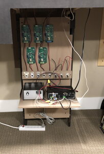
On my layout I have divided the layout into 8 "blocks" that are relatively large portions of the layout, not the same concept as DC blocks. I may have multiple trains in one DCC block. I have one circuit breaker for each DCC block and an on-off toggle switch for each block. That way if somebody shorts something out in one area it won't stop operation in another and I can completely shut off power to any section of the layout for trouble shooting, construction, etc. Each block or section has its own bus, there is no one single bus supplying the whole layout. That way if I cut power to one bus, the other busses can be powered.

Here is my power distribution panel (its an older picture, the remaining circuit breakers have been installed). It is visible from the door, so when I leave the RR room I can see if I left the power on and easily see if there is a short someplace. On the shelf at the bottom is my NCE command station, above the row of block switches, then the circuit breakers and the busses run out the top.
 

Attachments

  • PowerBoard.jpg
    PowerBoard.jpg
    202.7 KB · Views: 129


Back
Top