Chef Waardevast
Member
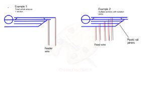
Thank you for the post it is very informative. I have a medium layout approx. 20m return. when I'am sectioning off an area must it be one track at a time? for example I have a rail yard that split's into multiple lines (see image below). Example 1 treats the whole area as 1 section. Example 2 treats the area as seperate blocks that are space by plastic rail joiners and power feed directly to each line, similar to a DC layout. Also I am using Insulfrog points by Peco not sure how that will affect dcc operation. I cant afford electrofrogs at this point.Sorry if my post caused any confusion. A smaller or even a medium sized layout doesn't require power districts or circuit breakers orblocking.
I was well on my way into wiring my modest sized DCC layout in a 16 x 12 room before I even knew much about districts, circuit breakers and the other requirements of a larger DCC layout. I have a centrally located Command Booster location and the DCC buss runs in two directions from the Command/Booster, no districts of any kind, no circuit breakers or additional Boosters on my layout.
Using blocking on a DCC can take several forms that include of which you have read about:
- Blocking sections of a yard to turn of power being routed to standing locomotives.
- Blocking of a layout for power districts.
- Blocking for the use of circuit breakers.
- Blocking for signals.
- And blocking for a reverse loop, if your layout has one.
- Blocking for combining DC and DCC on a single layout.
- Blocking for DC layouts and Cab control.
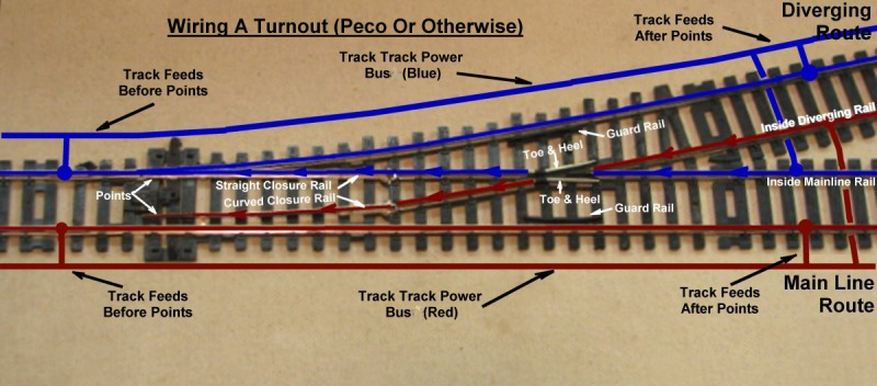
Using the term blocking when referring to feeders is confusing to those new to DCC. I think for DCC users using the term "Sectionalizing" would be a better term than blocking and leave blocking to DC users. Feeders are installed to lengths of track between rail joiners and are connected directly from the buss to the track. On a simple DCC layout the buss feeds all the track via many feeders without the need for any electrical switches. A simple loop of track could and would operation with one or maybe two sets of feeders
The purpose of a feeder is to supply the power and DCC signal to sections of track and not worry about a loose rail joiner (or the diverting side of a turnout) that would interfere with the power transfer and DCC signals and secondly help reduce power drop along the rails in long sections of track on a larger layout. Its recommend to solder each rail joiner.
Take a look at "Wiring for DCC"on the internet.
DCC helps keep every thing simple.
Hope this helps.
Greg
######################
wiringfordcc.com