ModelRailroadForums.com is a free Model Railroad Discussion Forum and photo gallery. We cover all scales and sizes of model railroads. Online since 2002, it's one of the oldest and largest model railroad forums on the web. Whether you're a master model railroader or just getting started, you'll find something of interest here.
Both #1 and 3 springs are single piece brass rod about .020 size. Rod is shaped like a square "C" with a loop in the middle to be screwed into the main frame from the top as can be seen on this picture:
From the horizontal sides i made bends which go straight down through the holes in the main frame with ends sticking out on the bottom to push against the axle. Very simple layout. The rear spring was a little more complicated because i had to hide the spring flush with the main frame so the motor would not be misaligned. I just soldered the shaped spring into a piece of brass plate, which was there under the motor already.
I will have to redo the #1 spring because it's just a little too stiff. But the idea is just to put a little pressure on the axle to push it down in track irregularities. I already filed a little crescent on the bottom plate so the axle can go down about 1/3mm. Those stiff all metal models sometimes have a tendency to lift the front axle and derail. I tried this first time on Bowser decapod and it works wonders and there's just enough pressure to push that axle down without pressing on it too much. The amount of pressure will be dictated by how much do the spring ends stick out into axle slot, so you can really fine tune the suspension. That decapod is really free rolling, so the spring really doesn't detract from running quality. I hope that answers your question.
Yep, thanks! Agree that suspension does help a lot. I have an 0-6-0 that is stiffer thank heck and it used to derail at a spot where something hit the rail and put a dent in it. If the suspended end hit that spot first, no problem. Go in the other direction and it would derail every time. I ended up replacing that section of rail vice taking the loco apart for that one.
This is the new look so far. I also decided to make a new spring for the #1 axle just like i posted earlier. The first shot has from left to right; number boards which get mounted on top of the boiler, earlier spring which i figured is too stiff, and finally new spring shaped to be more giving;
Rear trailing wheel set is not mounted yet.
I couldn't find the oxide brown for the roof, so i brush painted "track rust" instead. Might be a little too bright so i'll probably shoot some delicate "grime" on that later. The only detail the tender got was a reflector. I could go crazy on the tender details, but i want to finish this 2-6-2 since more interesting projects are in my head, and original intention was only to make this run well
I’m just catching up with all your work, quite inspiring thanx!
I only have one steamer, (it’s an old brass one), I think I might have to dust it off and put it on the rails…
I’m just catching up with all your work, quite inspiring thanx!
I only have one steamer, (it’s an old brass one), I think I might have to dust it off and put it on the rails…
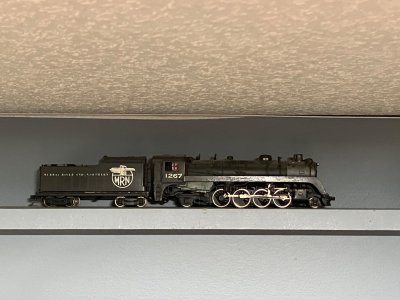
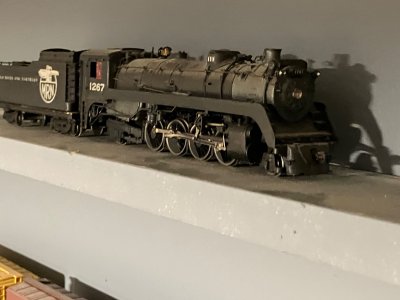
I believe that is a Van Hobbies Canadian Pacific P2 class 2-8-2 like this photo I found on Brass Trains. I like the freelance road name on yours though, I like the logo on the tender. It's a nice looking engine.
Is it possible to make a suspension too soft on a model steam locomotive?...yes it is. The drivers have so much up and down play that the locomotive is literally acting like a real short wheel base locomotive, it's all over the place because of working main and side rods. But it's just too much rocking to the sides and I'll have to do some more fine tuning on that. The up side is, this thing is not derailing even at full speed on the mainline, which was a major problem before i took the thing apart. The look so far:
Just a small exercise in chopping up plastic today:
After a brush wash in isopropyl alcohol it was time to cut up the Shark:
Maybe tomorrow i'll do the flat roof section to connect both pieces back up. The idea is to kitbash an E3b experimental electric locomotive, which worked for Pennsylvania Railroad back in 1950s and into early 1960s:
The top one is E2c (sometimes referred to by railfans as E3c). Bottom one is E3b. Two units of each model were built by Baldwin-Westinghouse in 1951, as a potential replacement for the railroads P5/P5a/P5b models. The exotic Bo-Bo-Bo wheel arrangement was one of just two known to me types ever to be used on American rails. The other electric type with three B trucks was the GM10B, build years later as a single unit for testing on Conrail, in hopes of selling the model for possible electrification west of Harrisburg, Pennsylvania to Pittsburgh.
I have to find a junk Kato/Atlas RS3. I already have one truck which i found on train show. After eyeballing it, it turned out to be the best size wise.