First decoder install ever... Intimidating.

ModelRailroadForums.com is a free Model Railroad Discussion Forum and photo gallery. We cover all scales and sizes of model railroads. Online since 2002, it's one of the oldest and largest model railroad forums on the web. Whether you're a master model railroader or just getting started, you'll find something of interest here.


Hello everybody.
A couple weeks ago one of my Kato ATSF GE Dash 9-44 CW, Nr 609 began emitting strange sounds, then the volume reduced progressively and finally disappeared !
Suspecting a speaker failure or a connection problem, I opened the shell for inspection.
I unsoldered and removed the speaker, then checked all wires for possible shorts.
I could not find anything but the decoder tabs are so close from each other, it doesn't take much to create trouble. And also I HATE SOLDERING, that doesn’t help either.
I sent a message to Soundtraxx and the answer was that I certainly killed the decoder amplifier. Probably a contact between a speaker wire and something else. Or the volume too high.
Since I set the volumes quite low, I would bet for a hidden contact.
I decided to put the shell back on and forget the now useless speaker, GE 609 found its place in a lashup beside sound equiped companions.
Two days ago I discovered in a box that I had another new identical decoder loaded with GE sounds, bingo !
I unsoldered the 609 decoder and installed the new one plus the speaker. I again adjusted all sounds, volumes and reverbs plus the DDE test run and all is back to normal.
Since I plan to equip a pair of Stewart F7 A and B units, they need the same PNP8 decoders, so I'll use the now silent decoder for the B unit, and use another PNP8 loaded with EMD sounds for the A unit.
That "sounds" good to me !

Brilliant, nicely done!
 
As I said previously I installed the decoder with the dead amplifier in a Stewart F7B unit. I removed it from a Kato GE dash9-44CW.
The decoder, a Blunami PNP8 was loaded with GE sounds. With its dead amplifier it still usable, without sounds, for any other loco using
PNP8 decoder. Such is the case for the Stewart F7B unit.
Later on I'll equip a F7A, also from Stewart, with a PNP8 decoder loaded with EMD sounds.

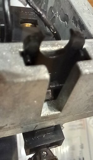
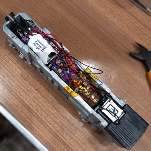
The original Stewart DC board is very easy to remove. Also, no weight in the way to remove.
I just soldered the two front and two rear rail pick-ups, and top and bottom motor contacts. That's it, I don't plan any lights on this B unit.

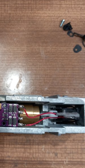
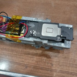
1974 : After removal of the DC board, and the now "silent" decoder ready.
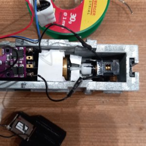
1975 : I glued some thin pieces of Evergreen to avoid any contact with the frame.
The decoder rests on a small square of double sided tape.
1976 : I installed a small piece of double sided tape between the two soldered rear cables, so they can't touch each other.

I'll install a current keeper later on.
 

Attachments

  • IMG_(1975).jpg
    IMG_(1975).jpg
    273.1 KB · Views: 21
  • IMG_(1976).jpg
    IMG_(1976).jpg
    336.2 KB · Views: 23
  • IMG_(1974).jpg
    IMG_(1974).jpg
    547.2 KB · Views: 24
Can the decoder be wrapped? Some recommend not to for heat, but wrapping the decoder ensures no contact with the frame or anything.


Can the decoder be wrapped? Some recommend not to for heat, but wrapping the decoder ensures no contact with the frame or anything.
Sincerely I don't know. I prefer to put one or two small pieces of double sided tape underneath, so it holds it in place and nothing can touch below.
I added thin Evergreen left and right because the frame is so high on the Stewart model. On other models there is no risk since it's surrounded by a plastic shell.
I use another small piece of double sided tape to hold the ultra flat speaker on top of the decoder, so there is no contact possible.
I also don't want to cover the Bluetooth chip, but is it important ?? The Blunami 2200 is totally wrapped in plastic, so...
 
Hello !
I am now waiting for a Blunami PNP8 with EMD sounds for my Stewart F7A, and 2 current keepers, one of them for the F7B unit equiped
with a now silent decoder. I also ordered a Scale Sound System speaker with an enclosure that fits the Stewart F7A.
I want to compare the sound with my ultra flat speakers.

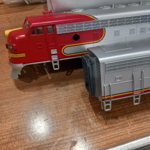
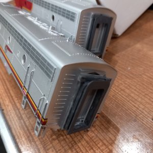
While waiting I decided to add details to those locos. Several years ago I installed wipers and American Limited diaphragms on both units.
I also painted the horns, I didn't like their plastic look. Then I put them back in their boxes for the future.
I now wanted to add all the vertical handrails and grabs these locos lack. I hesitated for a long time since it's quite a work.
There are a total of 34 pieces to form, different sizes, and 68 holes to drill !! 36 on the A unit and 36 on the B unit (only vertical handrails on B).

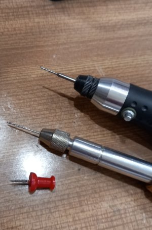
I used very stiff and thin metal wire formed with pliers and cut to size. There are VERY tiny marks on the shells, so I drilled the holes in three
steps : first a push-pin to accentuate the marks, then I made pilot holes with a hand drill, then I pierced the holes using my small Proxxon
power drill, hoping I wouldn't make a mess.
I painted everything before installation. I also painted some details on the body, like fuel fillers, marker lights and so on.
I also painted the diaphragms dark grey, they were very light grey, wayyy too light.

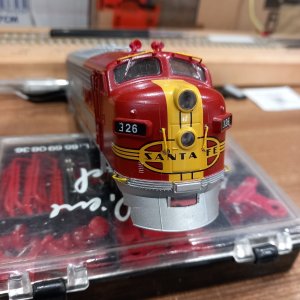
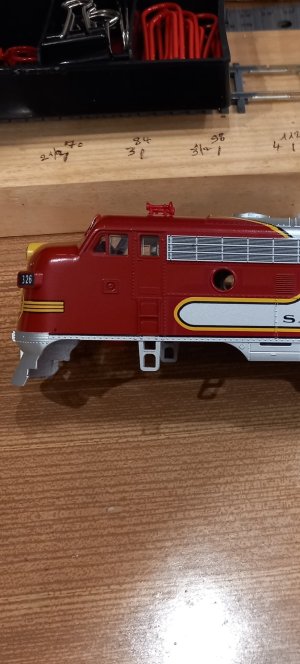
Attached : The tools, and some before and after photos.
 

Attachments

  • IMG_(1977).jpg
    IMG_(1977).jpg
    286.7 KB · Views: 25
  • IMG_(1978).jpg
    IMG_(1978).jpg
    284.1 KB · Views: 25
  • IMG_(1985).jpg
    IMG_(1985).jpg
    463.7 KB · Views: 22
  • IMG_(1979).jpg
    IMG_(1979).jpg
    281.7 KB · Views: 23
  • IMG_(1981).jpg
    IMG_(1981).jpg
    727.2 KB · Views: 25
  • IMG_(1982).jpg
    IMG_(1982).jpg
    427 KB · Views: 30
HI !
I received the current keepers for my F7A and B units, and also the decoder for the A unit.

I first installed the current keeper in the B unit, just a matter of plugging it to the already installed decoder. As I explained earlier the
decoder is now "silent", so no speaker needed. There is plenty of room in the B unit for the current keeper.

The A unit decoder received is a Blunami PNP8 loaded with EMD sounds. Since I wanted the decoder closer from the front of the loco,
I cut short the light "tube" to get more room.
 

Attachments

  • IMG_(1959).jpg
    IMG_(1959).jpg
    283.5 KB · Views: 14
  • IMG_(1960).jpg
    IMG_(1960).jpg
    210.3 KB · Views: 17


I prepared the decoder, installed it on two small pieces of double sided tape, and connected the wires : rails pick up, motor, front light
and speaker. With the decoder moved toward the front and after cutting off the plastic rear "light support" (useless in the A unit), I could then install the Scale Sound speaker easily.
This speaker is thought for those Stewart F7A units. First time for me, I wanted to compare the sound with my ultraflat speakers.
I plugged the current keeper and guessed it could sit on the front part of the decoder.

WRONG ! Impossible to put the body shell back on ! Gasp !

1984/85 : The plastic light support shaved off.
1986 : The finished installation that actually doesn't work !
 

Attachments

  • IMG_(1984).jpg
    IMG_(1984).jpg
    107.6 KB · Views: 18
  • IMG_(1985).jpg
    IMG_(1985).jpg
    134.7 KB · Views: 25
  • IMG_(1986).jpg
    IMG_(1986).jpg
    579.9 KB · Views: 20
I decided to build some kind of platform for the current keeper between the decoder and the speaker, just above the rear flywheel.

But even so I could not totally put the shell back on. I had to admit there isn't enough room for both, speaker and current keeper.
Well ! I removed the speaker, installed the current keeper on top of the rear "tower", and connected an ultra flat speaker which sits
on top of the current keeper with a thin piece of double sided tape.

I have two of those SSS speakers, hopefully I'll find locos with room for them.

1987/88 : Building the (useless) platform.
1989/90 : Current keeper finally installed, and the speaker on top of it.
 

Attachments

  • IMG_(1989).jpg
    IMG_(1989).jpg
    384.4 KB · Views: 18
  • IMG_(1990).jpg
    IMG_(1990).jpg
    551.3 KB · Views: 16
  • IMG_(1988).jpg
    IMG_(1988).jpg
    395.3 KB · Views: 17
  • IMG_(1987).jpg
    IMG_(1987).jpg
    430 KB · Views: 21
Hello everybody.
Recently I bought for a good price a Proto 2000 GP30, it looks pretty good and was weathered by the previous owner.
I plan to install a Blunami decoder and a speaker.
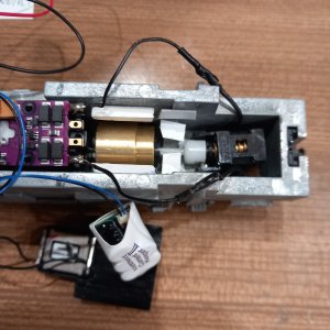
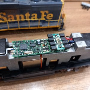
I opened it and, see the photos, this is how it was equiped, there is an 8 pin plug.
I don’t understand what I see, help will be appreciated.
Sorry for my lack of knowledge.
 

Attachments

  • 20260822_162904.jpg
    20260822_162904.jpg
    487.2 KB · Views: 26
  • 20260822_172119.jpg
    20260822_172119.jpg
    560.9 KB · Views: 23
What you see in the pics is the Proto2000 8-pin wiring harness "on top", with what looks to me to be a (not "factory installed") dcc decoder "underneath".

Have you tried running it on dcc?

If it IS a decoder (certainly looks far more complicated than a factory installed light board would look), and the engine runs well with it (even without sound), why not just leave it in place?
 
What you see in the pics is the Proto2000 8-pin wiring harness "on top", with what looks to me to be a (not "factory installed") dcc decoder "underneath".

Have you tried running it on dcc?

If it IS a decoder (certainly looks far more complicated than a factory installed light board would look), and the engine runs well with it (even without sound), why not just leave it in place?
Thank's for your reaction.
I can't try on dcc, I chose to stick with dc.
Big layout that would need an expensive dcc system.
The reason I chose Blunami decoders. I already equiped 7 locos.
If it is another brand of decoder I can't use it on dc. With Blunami I can run on dc with the advantage of dcc, just with the app on my phone.
Zooming on the 1st photo shows a Digitrax component.
You are right, it could very well be a decoder on which the original harness is plugged.
Now I have to see what Blunami could fit and find room for a current keeper and a speaker.
It gonna be tight !
Thank's again for your help.
 
Proto 2000 did their connections reversed by making locomotive connection as an 8 position floating socket vice making a board. The rail + -, motor + -, head/tail lamps are on that floating socket. The issue is that the DC board that used to be there had diodes to reduce the voltage and current to the lamps. I'm guessing the digitrax decoder does this as well. This my GP30 that I was replacing the lightboard. The green board at the top was what it came with. A stack of diodes for the lamps.

KATO BOARD FIT.jpg


If you keep that floating socket, then you will need to add a resistor to the lamps if you just plug an 8 pin decoder to it.
NMRA 8 PIN SOCKET.jpg

Add a resistor to pin 2 and pin 6.
 
Last edited:
Thank's Kusojiji, very precious infos.
It's certainly some kind of Digitrax decoder, so I'll remove it.
I think the best Blunami would be the Blu 2200 with an 8 pin to 9 pin adapter (photo 1846a (3) ).

The first photo in my previous post shows 4 removable plastic tabs covers on the "floating" board, could they be of any use ?
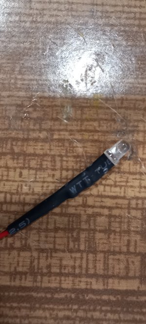
I have some diode equiped leds (photo 1903), could I use them to replace the original bulbs which don't look like leds ?

I thank you beforehand.
 

Attachments

  • IMG_(1846a) (3).jpg
    IMG_(1846a) (3).jpg
    537.7 KB · Views: 11
  • IMG_(1903).jpg
    IMG_(1903).jpg
    295.7 KB · Views: 12
Those plastic caps are used to hold the wires on. Here's how they work.
The cap has a notch on one side.
TAB AND CAP.jpeg


The wire is inserted into the hole on the tab from the side without a runner contact.
WIRE IN HOLE.jpeg


Then you push the cap on with the notch on the wire insulation side.
CAP FULLY ON.jpeg


The wire gets trapped against the electrical runner on the other side.
CONTACT SIDE.jpeg


Folks normally recommend soldering the wire directly to the tab and not using the cap, but I've never had any issues.

For the LED, since it already has a resistor built in, that makes it easy. From your photo, that arrow is pin 1. It should have an orange wire on it. Pin 2 is where you'll connect the tail light LED -. Pin 6 is for the headlight LED -. Pin 7 is for the head and tail light LED +.
8PIN FLOATER.jpg


Before removing the caps, verify that the lamps are connected to these tabs/pins. But from your other photo, it looks to be correct. Pin 2 should be a yellow wire, pin 6 is white and pin 7 is blue.


Soundtraxx BLU-PNP8 decoder might work in a Proto BL2:
Soundtraxx.jpg

It does fit right into Proto1000 RS3, RS11 and Proto2000 GP30, SD7/9.

Looks like it requires a space for installation about 75mm long (measure to be sure).
Depends on how much of a "cutout" is "on top" where the old light board is.

I use the Soundtraxx MC2H104at (motor only) decoder in a number of my Proto2000/1000 engines. Works just fine.


Affiliate Disclosure: We may receive a commision from some of the links and ads shown on this website (Learn More Here)

Back
Top