
You are using an out of date browser. It may not display this or other websites correctly.
You should upgrade or use an alternative browser.
You should upgrade or use an alternative browser.
Twinwoods & Bedford
- Thread starter RudyB
- Start date
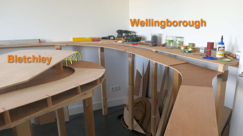
That's very true Dave, we'll give it a nice circle shape there, that'll create extra table surface. It's not that the current point shape is difficult to make, rather the opposite. It looks like a point in a table, but actually it isn't ... it's the spot where the two tables that are on different heights start to overlap. The lower table goes to the wall ... to create the circle will be harder. ")
What I was looking at is if you add facia on the layout and make the bottom of the fascia a consistent height from the floor, trying the screw anything in the fascia back in that vee will be next to impossible, you can't get a drill in there. I guess I am looking at it from an American construction approach where there isn't necessarily a "table" per se, you have roadbed under the track but the scenery isn't necessarily tied to the roadbed shape.
On another note, it is too bad you can't extend a track across the doorway and then to the left from Letton (which apperas to be the lowest levels) going under Bedford, to allow you put several staging tracks to store equipment and alternate trainsets.
On another note, it is too bad you can't extend a track across the doorway and then to the left from Letton (which apperas to be the lowest levels) going under Bedford, to allow you put several staging tracks to store equipment and alternate trainsets.
Twinwoods & Bedford - 04 - Simulation with EEP
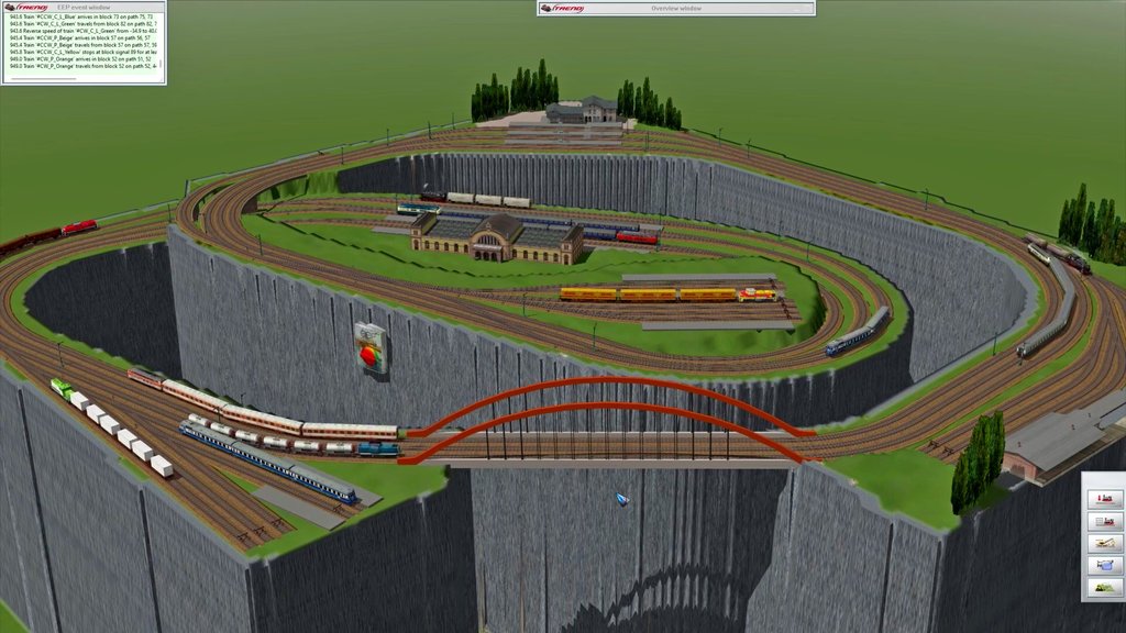
Before putting the saw into the wood, constructing tables and laying track we planned to do two simulations, one in Traincontroller and one in the very nice EEP 3D (model)railway simulator, which this video is about.
Any possible issues found in this stage will be much easier to resolve than after the tables are mounted and track has been laid. Besides … it’s just fun to create a layout in EEP and have trains run fully automatic, thanks to the additional software that was created in a joint cooperation with German hobby friend Frank Buchholz.
So … what are we looking for? Well, mainly if the layout looks nice … in our eyes that is, some will think there’s too much track and too little scenery, but that’s how we like it. We also want to check if train flow is smooth, varied, and without any traffic jams or hiccups, or opposite to see if there are any tracks that are never/seldom used.
This is the link to video Twinwoods & Bedford - 04 - Simulation with EEP
For those who like to try out EEP:
This is a link to EEP on Steam.
This is a link to the free EEP Automatic Train Control software.
This is a series of videos on EEP automation
Before putting the saw into the wood, constructing tables and laying track we planned to do two simulations, one in Traincontroller and one in the very nice EEP 3D (model)railway simulator, which this video is about.
Any possible issues found in this stage will be much easier to resolve than after the tables are mounted and track has been laid. Besides … it’s just fun to create a layout in EEP and have trains run fully automatic, thanks to the additional software that was created in a joint cooperation with German hobby friend Frank Buchholz.
So … what are we looking for? Well, mainly if the layout looks nice … in our eyes that is, some will think there’s too much track and too little scenery, but that’s how we like it
. We also want to check if train flow is smooth, varied, and without any traffic jams or hiccups, or opposite to see if there are any tracks that are never/seldom used.This is the link to video Twinwoods & Bedford - 04 - Simulation with EEP
For those who like to try out EEP:
This is a link to EEP on Steam.
This is a link to the free EEP Automatic Train Control software.
This is a series of videos on EEP automation
This looks very interesting! I see German rolling stock on the rendering but the names of the places sound very English - is this an international collaboration?
Will be fun to see this layout running under computer control. I am building a small portable computer-controlled N scale layout myself. Rather than using Railroad &Co, I will be writing the control software myself.
What will you be using for train position feedback? Current draw detectors or reed switch/Hall effect sensors?
Yes, 'Kleiner', it's an international project.
We're going to use reed switches. We find them more flexible in their use than current detection. We don't have to plan their positions in advance and don't have to think about the extra insulators and color coded drop downs while laying the track, or the extra high current diodes in the main DCC line. Their reliability has proven to be 100% over the past years that we've been using them.
We're going to use reed switches. We find them more flexible in their use than current detection. We don't have to plan their positions in advance and don't have to think about the extra insulators and color coded drop downs while laying the track, or the extra high current diodes in the main DCC line. Their reliability has proven to be 100% over the past years that we've been using them.
Twinwoods & Bedford - 05 - TrainController
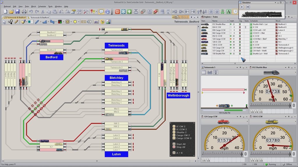
The second test before sawing the tables is to try the layout in TrainController. TC is a Windows program for control and automation of digital model railways. It has a simulator mode which makes it possible to already test a layout before it is physically there.
TC uses block control. Every block has an entry sensor. These can be reed switches operated via a magnet under the train, or current measurement, or other. The sensors tell TC when a train runs into a block. If it has to stop in this block, the brake marker is the point where the train starts to slow down, until it reaches the stop marker. Distances between the sensor and the brake- and stop marker are user specified.
Once the layout has been divided into blocks, ‘Schedules’ can be defined. These specify which trains should drive where. Once the train reaches the end point of the Schedule, TC selects a new Schedule from a list of ‘successors’. This way fully automatic traffic is created, while it still is possible to drive trains manually, in between the automatic traffic.
The test is performed to see if traffic keeps flowing, if there are no hiccups, or deadlocks, or if there are blocks where no train ever comes. All went well … so … it’s time to start sawing the tables!
This is the link to video Twinwoods & Bedford - 05 - TrainController
santafewillie
Same Ol' Buzzard
50 cm is still pretty tight, but probably doable. In US measurements, that's 19 5/8". One must be pretty comfortable passing a partner in that space!we now have a 50 cm aisle width.
Over 50 TC videos are available here:
Twinwoods & Bedford - 06 - Sawing the Table
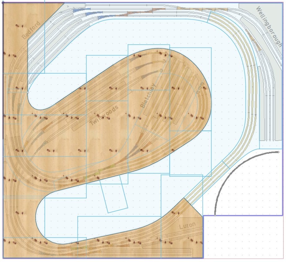
The two simulations (EEP video 4, TrainController video 5) showed us that this layout can have an interesting train traffic flow. This gave us the confidence to now start sawing the wooden plates for the table.
The challenge was to transfer the drawing from the PC to the boards to have the lines to saw along. We did this by first placing a grid of boards over the layout drawing. This enabled us to read out the x,y coordinates of strategic points per board. Two points are needed for a straight line, three for a curve. We used a bendable plastic strip to draw smooth curved lines on the board.
This is the link to video Twinwoods & Bedford - 06 - Sawing the Tbale
Twinwoods & Bedford - 07 - Mounting the Table
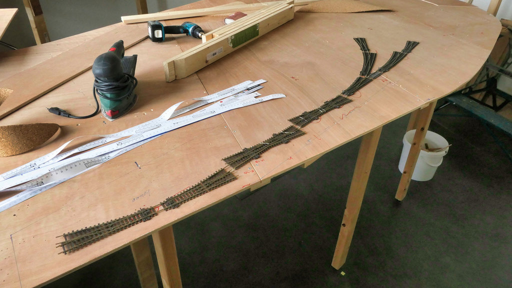
After having sawn the 9mm wooden plates in their respective shapes the tables can be mounted.
Along the wall the plates rest on a full length beam. The peninsula and the aisle side of the tables rest on legs, connected via beams to create a support frame. All legs have height adjustable feet.
In the meantime the lower and upper tables and the peninsula are mostly done. What’s left are the two ramps. These will be sawn out of 3mm board because they need to be flexible. The ramps are curved and need to be twisted some to mount them flat to the surface at both sides.
This is the link to video Twinwoods & Bedford - 07 - Mounting the Table
Twinwoods & Bedford - 08 - The Table is Ready!
This week a hardware milestone has been reached: the woodwork for the table is finished.
The bridge that can be opened at the room entrance has been mounted with two hinges on one side and a sliding lock at the other.
The two ramps are height adjusted and supported to the mm. One has a 2% inclination, the other 3%, we trust trains will be able to drive OK on these.
A few pieces of cork layer still have to be placed and then … let the track laying begin!
This is the link to video Twinwoods & Bedford - 08 - The Table is Ready!
Twinwoods & Bedford - 09 - A Paint Job & Turnout Servo Mount
We experimented with several rail bed and ballast options. We don’t plan to ballast the tracks 100%, which we know looks best, but we’re not that much into scenery and 100% ballasting is going to be a whole lot of work. We think we found a nice compromise that’s a lot less work and which also doesn’t require a second layer of cork under the tracks to heighten it.
The only thing needed is to paint the cork in a dark brown / rusty color, to which later maybe some spots and streaks of darker almost black can be added to taste. So … that’s what has been done past week, the cork has been painted with a Palissander stain.
The first track pieces and turnouts have been placed too, accurate to the mm. The video shows how we do the turnout servo drives.
This is the link to video Twinwoods & Bedford - 09 - A Paint Job & Turnout Servo Mount
Last edited:
Twinwoods & Bedford - 10 - Turnout Servo Drive
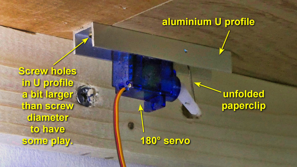
This video shows the servo drive we use on the layout in more detail. The servo motor is an SG90 180°. It fits snugly in a 15mm aluminum U profile, in which two screw holes are drilled as well as a 1mm hole that serves as the pivot point for the pin that moves the turnout. The pin is an unfolded paper clip.
We use Arduino for DCC control, loaded with the MARDEC software that can be downloaded for free from www.arcomora.com. This software is a DCC servo- and accessory decoder and it’s also used to tune the required servo angles for the two turnout positions.
This is the link to video Twinwoods & Bedford - 10 - Turnout Servo Drive
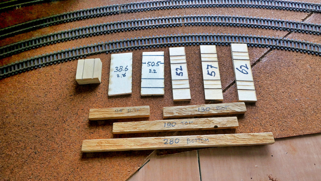
Twinwoods & Bedford - 11 - Laying Flex Track
We use Peco HO 75 track, which consists solely of flex tracks. To lay the flex track we use a couple of helpers like:
- A carton, cut in a circle of the desired radius, to lay circles
- A wire connected to a center pin, to lay circles
- A flexible plastic strip, to mark non circular curves
- A 15mm aluminum U strip, to lay straight track
- Different lengths of hardwood, to lay shorter pieces of straight track
- Track spacing jigs, to lay multi track stretches with high accuracy constant spacing
This is the link to video Twinwoods & Bedford - 11 - Laying Flex Track
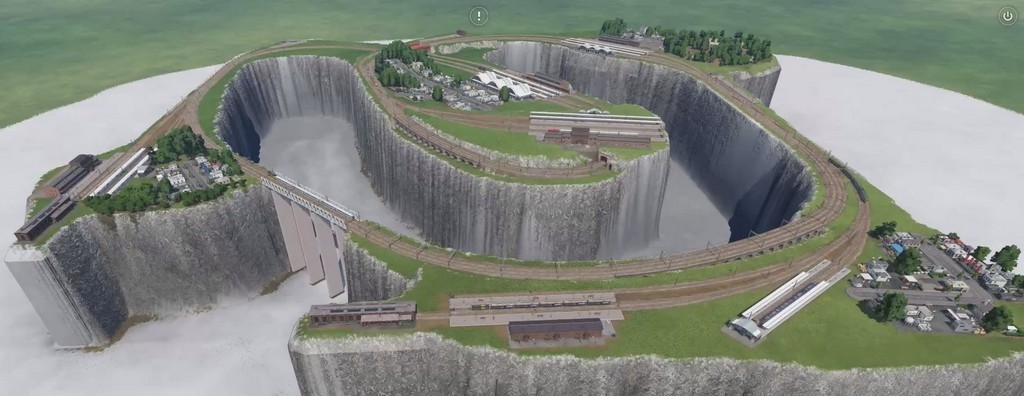
Twinwoods & Bedford - 12 - Simulation in Transport Fever 2
While Transport Fever 2 in fact is a logistics management game with the focus on setting up road- and rail transport between industries and towns, earning money and seeing the population and the economy grow and prosper, it can also very well be used to simulate a (model) railroad.
That’s thanks to the graphics, which are very nice. The user interface is OK too, creating a layout with automatic train and road traffic is not very hard to do.
The bonus is that it’s not just fun to do and results in something nice to watch, but to see in advance how a model railway layout is going to look once built can save hours of work and maybe material waste if changes are to be made. Once the building has started changes probably have far more impact.
This is the link to video Twinwoods & Bedford - 12 - Simulation in Transport Fever 2
Twinwoods & Bedford - 13 - Test Driving 11 Trains
Track laying, DCC wiring and sensor wiring are all finished. It’s time to test drive the layout with 11 trains.
The layout is computer controlled with Traincontroller 10. A separate series of videos on TC is available here.[/url']https://www.youtube.com/playlist?list=PLyC6aoYnRBZa8wmB0mXyYGjkb3050iUe6]here.[/url]
The DCC Command Station is a Digikeijs DR5000, combined with a DR5033 booster.
The turnouts are switched with SG90 servo motors, connected to DCCNEXT decoders, that can be acquired at about €10,- via arcomora.. The software, called MARDEC, is free.
Train detection is performed with reed switches on the track and a small Neodymium magnet under the train. The reeds are connected to Arduino Loconet shields that can be acquired at about €6,- via arcomora.. The software, called ARLOCO, is free.
This is the link to video Twinwoods & Bedford - 13 - Test Driving 11 Trains
