Twinwoods & Bedford


RudyB

Active Member
Twinwoods & Bedford - 01 - Layout Design

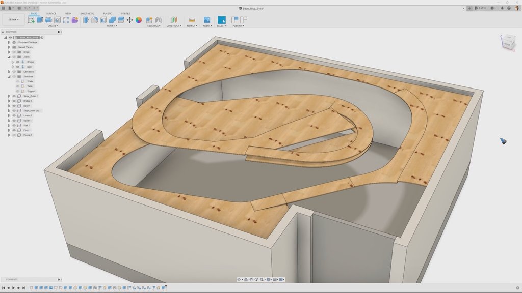
Together with hobby friend Nico the plan is to build a new layout in a spare bedroom. In this thread we like to post progress from time to time. We’ll go through all the steps, from first ideas, to design, to (3D) simulation, to woodwork, to track laying, mount point servo’s, add train feedback and create computer control. The plan is to add some videos along the way too.

No scenery in that list? Well … to be honest, creating beautiful scenery is not our forte. To us the emphasis of the hobby lies on the design, woodwork, track laing and then the automation. We’ll probably drive around with too many trains on too much track to make it look like anything ‘real’.

This is a link to video 01 - Layout Design

These were our criteria:
  • Available space: 4040 x 3700 mm
  • Scale: HO
  • Rail: Peco OO 75
  • Minimum radius: 600 mm
  • No need for much scenery
  • We like to have a lot of rails
  • It doesn’t have to resemble real world
  • We like to be able to drive around on a loop
  • We also like to drive dead end to dead end
  • We like to have a train viaduct, it enables a longer available track in the same space

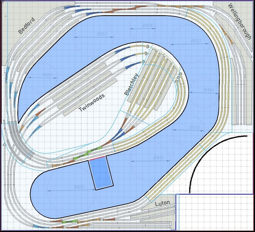
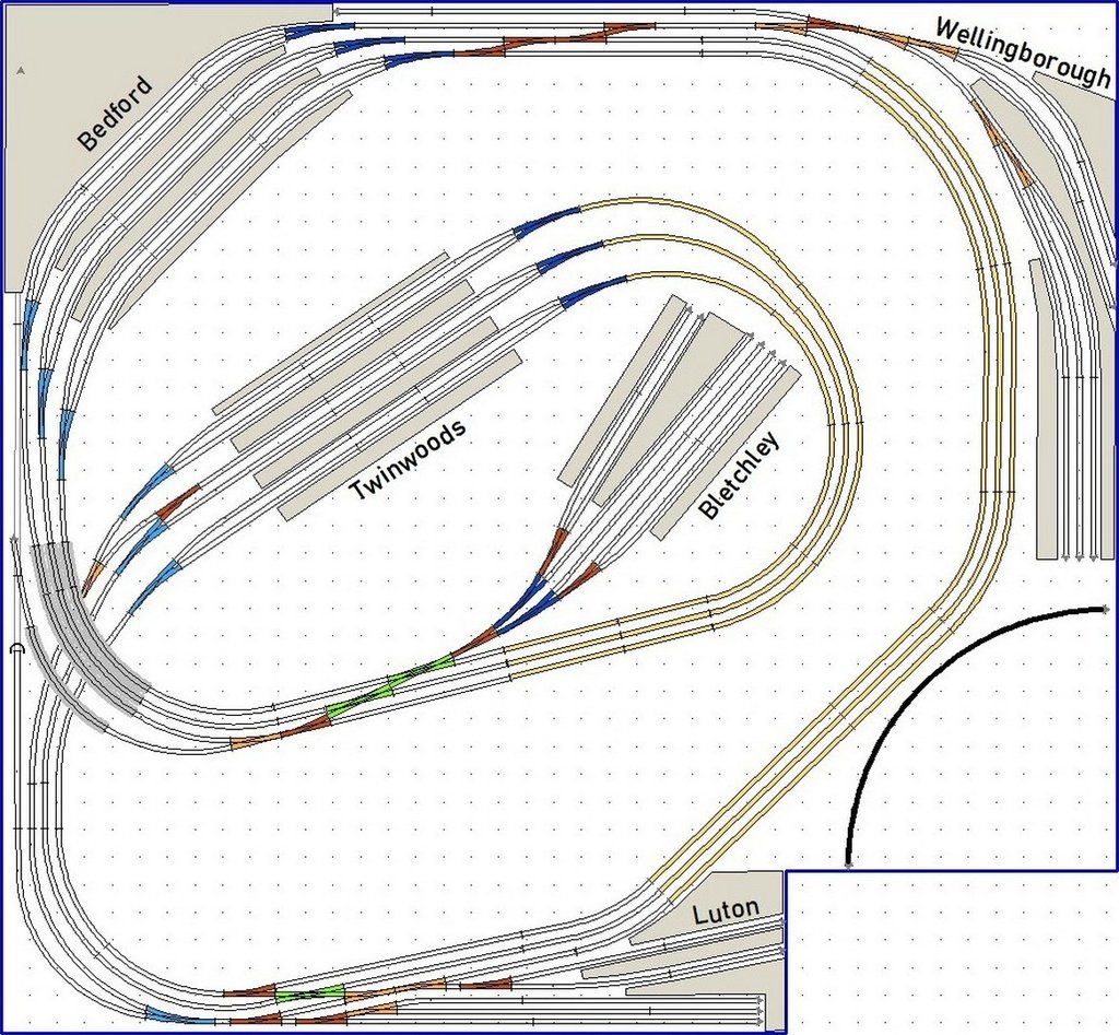
This is the end result of our design efforts:

44170641dq.jpg
 
Last edited:
There was a US book back in the 60's entitles "Six HO Railroads YOU Can Build." Of the six, it was number five which was my (then) dream layout: The Granite Gorge and Northern, and it was because someone here is building his own version of that layout that prompted me to join this forum in the first place.

The book was written by John Armstrong, and it was based on sectional track designs and Atlas components. But among the various thoughts John offered in his opening to the book was this gem, which has stuck with me for fifty years: "Even if you had a million dollars and the entire Los Angeles Colosseum* to build in, you would still have to make compromises to get close enough to see the trains." Which might apply here?

[* LAC is an American football sized stadium, although is might be sized for soccer too. In any case, I'm sure you get the idea]

I'll assume the quarter circle lower right is a door sweep...(so far so good)...but there is no clear aisle structure by which you intend to get close enough to see the trains, and reach the trains. I can see some areas where you intend those, perhaps, but it's unclear as to width, length, etc. Those are ESSENTIAL, because we humans are not HO scale.

I will assume too, based on station names alone**, that this is based on UK railroads, so the overall plan as concerns traffic density seems alright, and you have allowed for continuous running, which is good right there, since you like to see the trains run. You also have no staging yards, which, on a plan like this, would just be a problem. Open, track level staging works just fine, IMO.

[**Bletchley, is just one]

Add some human sized aisle access, and I can comment more usefully...but otherwise, the overall track design is good. :D
 
Thanks for your feedback Snowman. The quarter circle South East indeed is the door. There is a track piece that is intended to be on hinges so we can enter the space between the tracks. The next video will be on a 3D design of the room where the woodwork and the walking area is investigated. It's sized between 75 and 35 cm ... tight but doable, we think.

The station names suggest we simulate a UK railroad, but they actually are no more than names. We liked them better than having to say Station One, or Station North-West. We also drive right handed, not left, although on this layout it can be swapped in the computer control without changing the track.
Right handed can be confusing at times. You have your single seat 60's BRM and Coopers, with left hand six speed gearbox (in the case of the BRM), and your (Continental influenced, I've always assumed) Porsches, also right hand drive, but with right hand gearbox...and your Lotus's (single seaters, but also right side shift)...

...it all gets a bit confusing. The BRM is throwback, I know, but it just confuses me.... :D

Oh...wait. You meant TRAIN driver....

-----------

Re: Your lift section. I will guess it's a long one, hinged at Luton and all the way across to the curves before Wellingborough, however, if you intend the lift section to be only that shorter section across from Bletchley, I think it might be a bit narrow, in terms of shoulder width.

If you DO intend it to be a stone arch type viaduct, do be aware that you will be lifting not only the top of the viaduct, but also the bottom of the watercourse-scenery section. This has to come up with the topside too, so the natural hinging spots are at the ends, where top and bottom can most closely meet. This will need to be accounted for in your lift design, and would be very problematic if you intend a break anywhere in the middle of the viaduct with scenery that drops deep (or even shallow) under the viaduct. So it's best to go with a lift section hinged at one end or the other, IMO, where one or the other end of the viaduct meets its respective abutment. Even then, you will need careful design, so as not to leave either top or bottom too exposed, and subject to fracture as someone passes through.

Largest station is behind Bedford, methinks, into the corner. Perhaps with streets angled off to both right and left...

...and an angled corner pub opposite the back side of the station.... :D

---------

Last: When you say "we" I'll guess you might face the issue of two operators passing one another at some point in your aisle plan, the wide section above and left of Luton station being the obvious place for such a pass. Minimum suggested width there, assuming a back-to-back pass would be on the order of 762 mm (30" US)....
 
Last edited:
As Snowman says - make isleways or at least access holes so you can deal with problems. That is the #1 issue.

Looks like you are leaning to passenger traffic only, which is fine if that is what you want. That said, I think I would only have two platforms for Bedford and Twinwoods which could allow a movement to get by the station without having to slow down for people on the platforms. If you do want some industries, I don't think you would want some freight rumbling through a platform either.

Staging for this is almost a *must* and could be accomplished by putting it under the current plan. Even having 3 or 4 tracks for holding trains could be enough. More would be better if there is room.

There is nothing set up to turn your engines at end points. Fixing that might be tougher.

Don't know what equipment you will be running, a 24" minimum radius might be to small for those long passenger cars and will cause problems. Think #6 switches for any platform access, I would not go smaller than that. Because of the inherent 'S' curves in crossovers, try to squeeze in #8's or bigger.

I do like the 'flow' of the plan. You have time to make some changes before it gets cast in stone. MR design is iteration after iteration to get things workable. You will probably give up parts of the plan changing to something better or easier to deal with. Don't worry, we all go through this and that is part of the game. Or, maybe the Zen of model railroading.
 
Looks like I am going to enjoy following another great thread! How are you planning this viaduct concept ?
 
Followup idea for hinged viaduct: If you hinge at, say, the left end and hinge again in the middle (just a bit above track height)...and provide a lock-in-place lock (like a door slide bolt) the right end to fix it closed...and then another slide bolt in the middle, but oriented along the tracks, and underneath (so you can reach it from both sides) then you could DROP the viaduct and scenery down and left so that the two halves stand vertical, with the two halves touching one another literally on the rail heads. Rail faces rail, two halves of the scenery below the the viaduct on the outsides when folded.

Allow enough space between left wall and the hinge and the whole thing might fit vertically, thus minimizing blockage of access to the aisles when folded into the open position....

Of course just standing it up vertically works too. :D
 
@ctclibby The plan is to have 6 passenger trains and 6 cargo. 3 in both directions/. The Cargo trains only drive forward on the main track. At every industry area there is an extra side track where these trains can run into, coming from the main track, or when they re-enter the main track. Alternatively there coule be a loc staioned ther to shunt and couple to a cargo train to change direction.

Unfortunately we don't have enough space for long trains with the HO scale in this room. Our passenger trains will only be a loc plus 3 wagons. We wuld have liked 5 or 6, but that would mean change scale to TT or N.
 
@BigGRacing Not sure if you meant the viaduct in the West, or the bridge on hinges that we need to build at the door. The one in the left will probably going to be a laser cut 'metal' frame hanging bridge. The hinged viaduct at the door we don't know yet, should not become too fragile a constriction because it has te be openen and closed any time someone wants to enter the room ... or they'll have to duck :).
 
@Snowman. Not sure if I understand what you meant, but our plan anyhow is to prototype the hinged viaduct and maybe try a couple of different pinciples before we decide on anything definitive.
 
Twinwoods & Bedford - 02 - Table Design

The track layout has round shapes. We like the tables to follow these rounds. This means a lot of saw work, with good accuracy.

The plan is to first draw the table lines on the wooden plates such that it’s easy to follow them with a jigsaw. We’ll first make a drawing with the correct dimensions in Fusion 360. Using a 10 cm grid we can transfer the table coordinates at the grid intersections to the wooden plates, on which we first also place the grid dots. Then we play ‘connect the dots' and we'll have the real size drawing on the wood.

The plus of using Fusion 360 is that once we have a drawing we can simply turn it into 3D shapes and get a good feel for how it’s going to look.

Another option could be to print the layout in real size via SCARM. But then to accurately place all A4 sheets on the wood and transfer them to saw lines is still a challenge.

We’re curious what other methods have been used to transfer the layout to the table and create accurate saw lines?

This is a link to video Twinwoods & Bedford - 02 - Table Design

44184663vo.jpg
 
I don't know about SCARM, although I suspect that you should be able to print a 1:1 on many sheets of paper and position them. You might not need to print the whole thing, maybe just the complex track arrangements and eyeball the connecting track(s). I would do the outside corners first, then move to the inner loop. Try and keep your isleways as wide as you can with no pinch points - put a 1:1 human in somewhere and move it around to check out space. You might find you need to move the RoW here and there to make humans fit. Reach in is another thing to watch. Most here suggest no more than 28" to 30" depending on table height; even less if you are reaching over scenery and/or buildings to fix something.
So far you have done a good job of the initial design - Keep posting - I am sure that folks with give their $0.02 worth.
 
@ctclibby Thanks for your feedback. Yes, with the SCARM print option there it's possible to select on the drawing which pages you want to be printed and which not, to avoid a pile of pages with (almost) nothing on them. I'm sure wexll find a way to transfer the drawing to the wood.

The walking space is simulated and also tried,. It's not very spacious as it is now, but doable ... we don't want to sacrifice curve radius for it.
 
Forgot about your asking of transfering from drawing to benchtop. I use XtrackCad which the drawing origin is the lower left corner and is 0:0. You can find any 2 points on the drawing of the benchwork, circle radius or switch location you want to place, then run a ruler or tape on the x and y coordinates @ 90 degrees to find that point on the layout floor or benchwook. I bought a couple of laser thingies to help with this as my layout is a tad bigger than yours. I even tried polar coordinates ( distance @ angle ) so I could just set the angle then run out for said distance. I found I did not have a good way to get the angle correct as I had no way to create a 3 to 4 ft protractor to give 1/4 degree angles for the resolution needed. So back to X:Y coordinates. Note that this is still not exact, although probably close enough.
 
Last edited:
This super low tech method is sure fire. Make a piece of paper the size of your room and place on the floor of the empty space. Cut to size, pencil all your curves, etc. Cut out the cut outs. All the track can be drawn on the paper. Cut the paper to usable size, making sure to identify the match lines. I used the paper template to cut out all my track supports. Also can stage your buildings on the paper template. Does not require a computer.

That is how I am bulding my layout and it sure worked slick!

Dave LASM
 
Thanks ctlibby and Dave for your input. The x,y coordinates is what we intend to use, or at least try out on a couple of wood plates that measure 60x120 cm. We grabbed a handful of these paper rulers they have hanging around at the local DIY shop, to use multiple rulers makes it easier to keep straight on a distance. We'll also try the paper (or probably a thin carton) as intermediate. After both tries I bet we'll be able to judge what works best for us.
 
That's a lot of railroad for just one or two people to operate. Your aisles look very tight, it will be hard to have two people move around in there let along more than two. US convention is to have the operators follow their trains as they move around, you may be shooting for a "tower" operation where the operators are always seated at the same place and hand the trains off to each other. I could see two operators doing that but three would be reaaaaaaally tight.
 
In English that would be about 12' x 13'. My layout is about 10' x 12' and shaped a lot like yours on the outside, except with the outside edges rounded. Also, kind of a trapezoid where the door comes in.

I have a walk around controller which plugs into 3 outlets staged around the layout. I have been operating it for about two weeks, since the track has been completed, and find that I usually only use one of the plugs and tend to stand close to the middle most of the time, except to do the manual switches or unhook cars.

ONE thing I found was having the round corners, I can both take photos and work on scenery from the corners of the layout, which greatly increased accessibility. Like where you have the word Bedford on your plan that would be a great place to be able to stand up and My layout is kind of high at 48" but really nice to duck under and work under.

I agree with Dave H. above especially in that you may want more room with the isles.
 
Dave H, that's a valid point ... if the plan would be to operate by hand with multiple people the walking space definitely is too cramped.

We plan to automate the layout though, using Traincontroller. One or two people can still hand operate their train to drive it from A to B, whereby the track signals are controlled by TC. Or the whole layout can still be hand controlled, but that will be done from the TC switchboard on the laptop.
 
Twinwoods & Bedford - 03 - Widen the Aisle

We had performed tests to investigate if we’d be able to pass through a narrow space of 30 cm. The tests were performed with two desks spaced 30 cm apart. The tests were positive, as in ‘it’s doable’, but deks are only 74 cm haigh, which means you pass them below your bum, with your legs. Yesterday we were able to perform similar tests with tables at the intended height of 110 cm … that’s a whole other matter. Now you pass the tables above your bum, with your belly. How come that does not fit nicely anymore? I have no idea. :)

Conclusion of the test was that we need to modify the layout. To create more aisle space we had to give up our criterion of a minimum curve diameter of 120 cm, we made the inner curve around Bletchley station 100 cm and we also created a small bend just after the turnouts into Bletchley. This had the desired result … we now have a 50 cm aisle width.

In the process the idea popped up to extend Bletchley station over the curve, creating a tunnel. This helps make the layout somewhat more interesting. It’s not decided yet … let’s say this has an 80% probability.

This is a link to video Twinwoods & Bedford - 03 - Widen the Aisle

44194729uk.jpg


Back
Top