Hi Lloyd,
Lets's take the SWITCH-8 device first...
It does essentially the same thing as the RR-CirKits MotorMan - each handles eight Tortoise switch machines (thus eight turnouts).
The retail price of the SWITCH-8 is $70 but I found it for $56.
The retail price of the BUTTON-BOARD is $30 but I found it for $24.
That's a total of $80 for controlling eight turnouts.
The retail price of the RR-CirKits MotorMan is $50.
That's a total of $50 for controlling eight turnouts.
Even if you add a RR-CirKits FOB-C board ($13) to simplify hooking up the push buttons that still only comes to $57 as each FOB-C board can support two MotorMan devices.
So even at retail the RR-CirKits MotorMan is less expensive then the SWITCH-8/BUTTON-BOARD combination at the discounted price.
And I feel safe saying the RR-CirKits MotorMan is a much more versatile device if you make use of some of it's advanced features.
Now are to the wiring diagram...
The diagram is correct but it is showing a lot at one time so it may be somewhat confusing.
The 3X connectors on the SSB devices (MotorMan, SignalMan, WatchMan, TowerMan) have nothing to do with powering your track via multiple boosters.
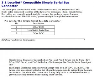
Each SSB device connects to another SSB device via three wires.
When powering them with DC one wire is the negative power lead, one wire is the positive power lead and the remaining wire is the "data" lead.
Now the SSB specifications say the boards can be powered from DCC as well.
I however avoid that as I prefer to have a separate source of clean DC power for powering electronic devices and leave the relatively "dirty" DCC power on the track, just running the trains.
If you recall I mentioned the SSB Gateway? It has the same pair of 3X connections. So you can connect the Gateway (if desired) to two different groups of SSB devices. Perhaps the Gateway device ends up in the middle of your layout. So you could use one connector on the Gateway to connect to the SSB devices off to the left, and the other connector to connect to the SSB devices off to the right.
The thing to remember is each 3X connector on the Gateway can connect to one SSB device (using the 3 wires), and that device will connect to the next SSB device (using another set of 3 wires, and so forth.
The last SSB device in the "chain" will just have the "incoming" connection from the previous SSB device.
Let's consider "stage one" of your layout wiring as manual only.
The SSB devices still need to be connected to one another using the 3 wire cable (or just 3 wires).
You wouldn't have to install the Gateway device or the LocoBuffer USB device for manual operation.
You could just connect the two power wires coming from the first SSB device in the "chain" of devices to a source of clean DC power (11 to 15 volts).
You could install a Gateway device as it provides a simple way to provide power to the SSB devices and it would already be in place when you wanted to proceed to "stage two" wiring - for computer automation.
Also remember that the MotorMan device is unlike the SignalMan, TowerMan and WatchMan devices in that it requires a second source of DC power to actually drive the Tortoise devices.
As you may recall this is done so you can used the required 11 to 15 volts DC for POWERING the various SSB devices but use a different voltage (5 to 25 volts DC) from a different power supply so the Tortoise units move at the desired speed - higher voltage, faster speed.
I am leaving town for a few days and need to spend some time today packing so I doubt if I will have time to draw any diagrams before I go but let's try to sum up...
- 3 wires (or 3 wire cable) connects each SSB device in the "chain" to the next SSB device.
- You can mix and match SSB devices - you do not have to have all of the MotorMan devices connected together then, say, all of the SignalMan devices connected together. Any SSB device can be placed at any point in the "chain", as you desire.
- A DC power source of 11 - 15 volts needs to be connected to the power wires at the one end of the "chain".
- A Gateway device can be used as a easy way to connect power the the SSB devices.
- A DC power source of 5 - 25 volts needs to be connected to the MotorMan devices ONLY, so as to provide power at the desired voltage for driving the Tortoise units at the desired speed.
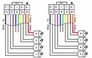
- 4 Tortoise devices connect to the MotorMan connector "OUT 1-4". (see attached)
- 4 Tortoise devices connect to the MotorMan connector "OUT 5-8". (see attached)
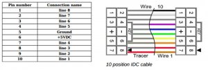
- 8 push buttons connect to the MotorMan connector "I/O-1". One wire from each push button will all be wired together in some fashion and connected to the GROUND pin of the connector. The other wire from each push button will be connected to the "line 1" through "line 8" pins of the connector.
- If desired a RR-CirKits FOB-C board can be used to provide compression connections for wiring push buttons.
- The flat cable and connectors for the flat cable are all available from RR-CirKits. It is VERY easy, with just a little practice, to attach the connector to the cable with a simple pair of pliers.
That has to be it for now - I have to run.
I will be in touch in a day or two.
Frederick
Lets's take the SWITCH-8 device first...
It does essentially the same thing as the RR-CirKits MotorMan - each handles eight Tortoise switch machines (thus eight turnouts).
The retail price of the SWITCH-8 is $70 but I found it for $56.
The retail price of the BUTTON-BOARD is $30 but I found it for $24.
That's a total of $80 for controlling eight turnouts.
The retail price of the RR-CirKits MotorMan is $50.
That's a total of $50 for controlling eight turnouts.
Even if you add a RR-CirKits FOB-C board ($13) to simplify hooking up the push buttons that still only comes to $57 as each FOB-C board can support two MotorMan devices.
So even at retail the RR-CirKits MotorMan is less expensive then the SWITCH-8/BUTTON-BOARD combination at the discounted price.
And I feel safe saying the RR-CirKits MotorMan is a much more versatile device if you make use of some of it's advanced features.
Now are to the wiring diagram...
The diagram is correct but it is showing a lot at one time so it may be somewhat confusing.
The 3X connectors on the SSB devices (MotorMan, SignalMan, WatchMan, TowerMan) have nothing to do with powering your track via multiple boosters.
Each SSB device connects to another SSB device via three wires.
When powering them with DC one wire is the negative power lead, one wire is the positive power lead and the remaining wire is the "data" lead.
Now the SSB specifications say the boards can be powered from DCC as well.
I however avoid that as I prefer to have a separate source of clean DC power for powering electronic devices and leave the relatively "dirty" DCC power on the track, just running the trains.
If you recall I mentioned the SSB Gateway? It has the same pair of 3X connections. So you can connect the Gateway (if desired) to two different groups of SSB devices. Perhaps the Gateway device ends up in the middle of your layout. So you could use one connector on the Gateway to connect to the SSB devices off to the left, and the other connector to connect to the SSB devices off to the right.
The thing to remember is each 3X connector on the Gateway can connect to one SSB device (using the 3 wires), and that device will connect to the next SSB device (using another set of 3 wires, and so forth.
The last SSB device in the "chain" will just have the "incoming" connection from the previous SSB device.
Let's consider "stage one" of your layout wiring as manual only.
The SSB devices still need to be connected to one another using the 3 wire cable (or just 3 wires).
You wouldn't have to install the Gateway device or the LocoBuffer USB device for manual operation.
You could just connect the two power wires coming from the first SSB device in the "chain" of devices to a source of clean DC power (11 to 15 volts).
You could install a Gateway device as it provides a simple way to provide power to the SSB devices and it would already be in place when you wanted to proceed to "stage two" wiring - for computer automation.
Also remember that the MotorMan device is unlike the SignalMan, TowerMan and WatchMan devices in that it requires a second source of DC power to actually drive the Tortoise devices.
As you may recall this is done so you can used the required 11 to 15 volts DC for POWERING the various SSB devices but use a different voltage (5 to 25 volts DC) from a different power supply so the Tortoise units move at the desired speed - higher voltage, faster speed.
I am leaving town for a few days and need to spend some time today packing so I doubt if I will have time to draw any diagrams before I go but let's try to sum up...
- 3 wires (or 3 wire cable) connects each SSB device in the "chain" to the next SSB device.
- You can mix and match SSB devices - you do not have to have all of the MotorMan devices connected together then, say, all of the SignalMan devices connected together. Any SSB device can be placed at any point in the "chain", as you desire.
- A DC power source of 11 - 15 volts needs to be connected to the power wires at the one end of the "chain".
- A Gateway device can be used as a easy way to connect power the the SSB devices.
- A DC power source of 5 - 25 volts needs to be connected to the MotorMan devices ONLY, so as to provide power at the desired voltage for driving the Tortoise units at the desired speed.
- 4 Tortoise devices connect to the MotorMan connector "OUT 1-4". (see attached)
- 4 Tortoise devices connect to the MotorMan connector "OUT 5-8". (see attached)
- 8 push buttons connect to the MotorMan connector "I/O-1". One wire from each push button will all be wired together in some fashion and connected to the GROUND pin of the connector. The other wire from each push button will be connected to the "line 1" through "line 8" pins of the connector.
- If desired a RR-CirKits FOB-C board can be used to provide compression connections for wiring push buttons.
- The flat cable and connectors for the flat cable are all available from RR-CirKits. It is VERY easy, with just a little practice, to attach the connector to the cable with a simple pair of pliers.
That has to be it for now - I have to run.
I will be in touch in a day or two.
Frederick