
You are using an out of date browser. It may not display this or other websites correctly.
You should upgrade or use an alternative browser.
You should upgrade or use an alternative browser.
M.E. Bridge beam parts?
- Thread starter Rico
- Start date
ModelRailroadForums.com is a free Model Railroad Discussion Forum and photo gallery. We cover all scales and sizes of model railroads. Online since 2002, it's one of the oldest and largest model railroad forums on the web. Whether you're a master model railroader or just getting started, you'll find something of interest here.


That was my thought too, just based on looking at them, but in that case, I’m confused on why they’re not full length, same as the girders?
I have seen some bridges that have a second plate part of the way, as reinforcements? I don’t know if that is anything related to this?


The kits can be used in more than one manner. You've used the additional parts as reinforcements, which is correct and prototypically accurate.
However, should you wish to model this span, you can cut a radius and then curve them to match. In fact, if you look closely, it shows both applications, your additional plates (top and bottom) and his radiused corner.


Affiliate Disclosure: We may receive a commision from some of the links and ads shown on this website (Learn More Here)
Selector
Well-Known Member
I think that they may be the parts you bend if you want the hipped (rounded) ends of the through girder type bridge. You radius, carefully, the end of the girders that will be over the abutments, and then match the flanges to the web, curved. However, when I made this bridge, you were to cut off the flange (maybe they provided extra flanging...it has been 15 years), and then heated and bent the flange down over the sculpted web, gluing it with MEK.
wheeler1963
Aurora & Portland Owner
Rick, I just built this kit for a flat car load. They go on the top and bottom of the girders.

Rick, I just built this kit for a flat car load. They go on the top and bottom of the girders. View attachment 47268
That was my thought too, just based on looking at them, but in that case, I’m confused on why they’re not full length, same as the girders?
I have seen some bridges that have a second plate part of the way, as reinforcements? I don’t know if that is anything related to this?
Alcomotive
Grandson of an ALCO Builder
They are simply called "sill plates" used as added reinforcements in the center of the structure to help deflect any sway or sag.
flyboy2610
Loveably weird
I like that idea!Rick, I just built this kit for a flat car load. They go on the top and bottom of the girders. View attachment 47268
kjd
Go make something!
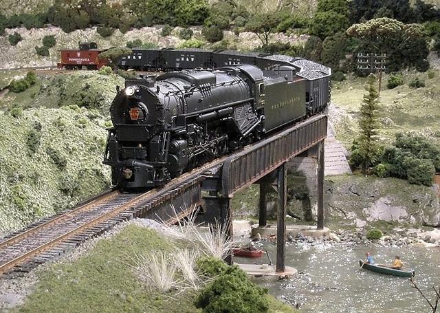
Dennis, it's true you don't have to bend anything but Crandell was talking about a particular style of bridge. On some plate girder bridges the corners are rounded, I guess to keep shifted loads or maybe derailed cars from directly impacting the end of the bridge. Maybe the curve will deflect an impact upward and limit damage to the bridge. Crandell modeled this in his photo of the plate girder bridge. Deck Girder bridges like in Jerome's photo will have square ends.
You do not bend anything.
You have sides which can splice together. Then the narrow parts go over the joint.
You need to kitbash or scratch build the deck and gussets.
I actually cut some plastic strips to go under the narrow pieces to make the splice longer
View attachment 47330View attachment 47331
The kits can be used in more than one manner. You've used the additional parts as reinforcements, which is correct and prototypically accurate.
However, should you wish to model this span, you can cut a radius and then curve them to match. In fact, if you look closely, it shows both applications, your additional plates (top and bottom) and his radiused corner.
Selector
Well-Known Member
The bridge that I show is the "150 foot combination bridge" that ME sells. I built this almost 15 years ago, so the details are fuzzy, but I seem to recall that the instructions said to cut off the end of the top flange, round the top corner of the web, and then to heat and bend-to-radius one of those strips, which are flange elements, or can be used as such.
Thanks for those images above, they really help to show how complicated a girder bridge really is.
Here is a better image, rather severely cropped to get up close, of that bridge on my original layout:
Thanks for those images above, they really help to show how complicated a girder bridge really is.
Here is a better image, rather severely cropped to get up close, of that bridge on my original layout:
kjd
Go make something!
I doubt it will bend without heat. It doesn't take much, styrene starts to soften around 150F. A few seconds in boiling water will be plenty. Wear something heat resistant on you fingers though. A test on an extra piece is always a good idea. Too hot and it will not stay flat, the edges will start to curl.Darn, I did not think of that: will that plastic bend without heat?
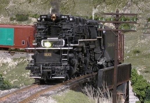
I was modeling one near me...
View attachment 47335
View attachment 47334
Affiliate Disclosure: We may receive a commision from some of the links and ads shown on this website (Learn More Here)