PolarExpressBill
New Member
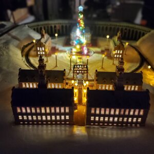
I have been making an N scale Polar Express Theater on wheels train layout. It is all 3d printed and uses ez track.
I wanted to add in a signal light for my turnout. After doing much testing and research, I found out that when I used my insulated frog, ( a piece of track that I acquired from a sale), that this setup will work. But on the layout I learned that I don't have insulated frogs and both turn outs have full powered frogs. Now without taking the track off the layout, is it possible to convert, modify or hack the full powered frog to act like the insulated one works. The pictures are just for reference to show you the layout. But the turnouts are for this post.
If I can't make this work, a possible work around would be a slider switch that is double pole and I would use this to simulate the green or red light as I manually switch the track during the show. I can make that work. This is all DC.
Thanks I hope you guys can offer me a very positive solution on if this if it is possible. This is my first post.
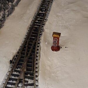
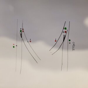
First picture (insulated frog) test that works.
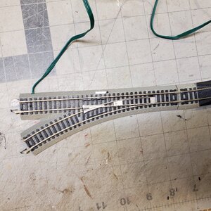
Second picture (full powered frog, test that does not work, but acts like an on or off for the lights.
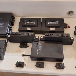
Third picture (working diagram for dwarf lights.
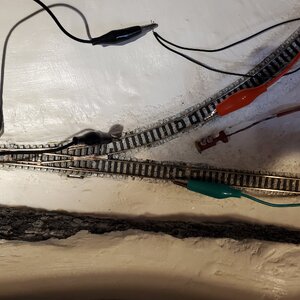
Fourth picture of where the turnout is for the layout.
I should add that I powered the track from the circle in the last picture, so if I do change the frog would that not allow power to the rest of the track or would could it weaken the strength of the signal for the entire track? There are no feeders.
I wanted to add in a signal light for my turnout. After doing much testing and research, I found out that when I used my insulated frog, ( a piece of track that I acquired from a sale), that this setup will work. But on the layout I learned that I don't have insulated frogs and both turn outs have full powered frogs. Now without taking the track off the layout, is it possible to convert, modify or hack the full powered frog to act like the insulated one works. The pictures are just for reference to show you the layout. But the turnouts are for this post.
If I can't make this work, a possible work around would be a slider switch that is double pole and I would use this to simulate the green or red light as I manually switch the track during the show. I can make that work. This is all DC.
Thanks I hope you guys can offer me a very positive solution on if this if it is possible. This is my first post.
First picture (insulated frog) test that works.
Second picture (full powered frog, test that does not work, but acts like an on or off for the lights.
Third picture (working diagram for dwarf lights.
Fourth picture of where the turnout is for the layout.
I should add that I powered the track from the circle in the last picture, so if I do change the frog would that not allow power to the rest of the track or would could it weaken the strength of the signal for the entire track? There are no feeders.
Attachments
Last edited: