ModelRailroadForums.com is a free Model Railroad Discussion Forum and photo gallery. We cover all scales and sizes of model railroads. Online since 2002, it's one of the oldest and largest model railroad forums on the web. Whether you're a master model railroader or just getting started, you'll find something of interest here.
Did some more work with the skirting on the layout.
I'm satisfied with it.
Now I have to figure out how to bring the scenery up to the edge of it but still be able to remove the panels if I need to get access to the wiring.
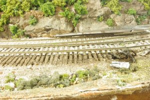
This isn't the prettiest picture in the world, but it gives the general idea. It looks like my layout has generally similar construction to yours, L-girder with cookie cutter roadbed, the fascia attached to some sort of falsework extending from the L-girder. I've found that if you do the standard cardboard strips-and-plaster cloth scenery between the cookie-cutter trackbed and the Masonite fascia, you can simply unscrew the fascia and pull if off. The cardboard strips and plaster cloth will stay in place. The joint between the fascia and scenery where I've done this at least once is visible at the lower edge of the photo. You then sprinkle a little scenery on the crack to clean things up when you're done.
Although maybe another way to look at things is to recognize that at your stage of construction, you'll no doubt need to pull the fascia more than once anyhow, maybe better to wait a little before adding it!
You're asking how to remove the panels if you want to get to the wiring, once you bring scenery up to the fascia. You appear to be pointing to the area a few inches wide between the cookie-cutter roadbed and the fascia. I'm assuming -- the photo doesn't show that level of detail -- that the fascia is screwed to some sort of falsework attached to the L-girder. Without scenery attached, I am assuming you can just unscrew the fascia panels, work on the wiring, and screw them back on when you're done. What I'm saying is that if you add scenery between the cookie-cutter trackbed and the fascia, once the scenery dries, it will keep its shape. That means that you can pull the fascia panels away from the scenery the same way you did before, it's not a biggie. Although of course, scenery is best done after you've done the bulk of the under-scenery work. Same would apply to fascia.
Hope this explains it, I was trying to answer the concern you raised!
It's the crack between the scenery and fascia at the lower edge. I know it was distracting that the photo showed track being pulled up, but it was the clearest thing I had on hand.
The edge connectors arrived yesterday for the three circuit boards along with the circuit breakers that go between the PS2012 power supply and the boosters.
One draw back with the edge connector for the SE8C is that it doesn't have a means of mounting it to the board. The other two edge connectors have holes in the circuit board for screws. I ran screws through the SE8C board itself to keep it on the back board. Also, there is not provision for common ground connection to the SE8C. I'll have to look at the instructions for the SE8C to see if there was originally a connection to the connector strip.
The second picture here is the push button circuit breakers. One button for the Command station and each of the boosters.
I finished dividing section 2 of the layout into detection blocks. Had to do some troubleshooting to find a hidden wire that connected both common rails of the double track mainline.
Built the loconet cables for each board.
Installed and setup the PM42 circuit breaker then set the address.
Installed the BDL168 and wired up both mainlines. Tested it with a loco and all is good.
I ran out of energy tonight and will power up the cross overs and industry turnouts tomorrow night.
Sure goes together quicker when ya know how to do it.
I'm using the Acculite edge connectors this time and it really helps to keep the wiring more organized and easy to make the connections.
Only half of the connections are used so far. I have two more detection sections to wire into the system which will use the remaining connection points.
The SE8C on the far right will be wired into the turnout motors and the track side signals when I get to that point. Hopefully by the weekend after Thanksgiving.
I was able to work on the layout tonight for a few hours before the Redskins game came on.
I wired, powered and installed the local pushbutton control for a crossover.
Installed a Tortious machine and ran power and push button wires for the turnout.
Wired the staging yard leads to the BDL168.
I'm curious -- given the JMRI-compatible signal system you're using (from what I think I understand), wouldn't you be using DCC accessory decoders to control your Tortoises? Or would that just be main line switches, and the push buttons on spurs, or what? Fascinating thread, it's bringing me up to date on all this newer stuff.
I'm curious -- given the JMRI-compatible signal system you're using (from what I think I understand), wouldn't you be using DCC accessory decoders to control your Tortoises? Or would that just be main line switches, and the push buttons on spurs, or what? Fascinating thread, it's bringing me up to date on all this newer stuff.
The Tortois machines get their power from the SE8C board just as it would be powered by a Digitrax DS64. The push button is wired into the SE8C board too and it can be toggled using the Digitrax DT402 handheld controller. The track of the turnout is powered from the BDL168 for block detection or it can be powered directly from the command station.
All the mainline is powered back up now in Section 2. The detection sections are established, now to start integrating the signal system into the section.
I'm having some difficulty here again and I need some help to confirm I have done all the correct steps so far.
I'm setting up the SE8C board.
The turnouts work using the local push button as well as the remote control using the DT402, plugged into the loconet as well as by radio link.
I have established the block detection using the BDL168 and have registered them on the Train Controller Silver and the Contact Indicator (CI).
I can see the CIs turn red as the loco moves into each detection section.
Now, with the SE8C. I gave this SE8C the board address of 2.
I plugged the short mast test strip into Drv1 and attempted to toggle the mast lights using TC Silver. They won't respond. I confirmed the board address using the turnouts as number 9, 10 and 12 and they work using those numbers using both the DT402 controller as well as toggling the turnouts using TC Silver. I only have three turnouts from the mainline in this section.
I am able to change the board address and the turnout numbers change accordingly but the signal mast still don't respond to the numbers that they should be.
I am considering swapping this board with the board that is working in section 3 to see it responds correctly there. I don't think it would change anything in the signal programming that I have already done in that section.
What are your thoughts on this?
I often will substitute a known good unit to verify wiring, etc.
I would also double check ALL settings for the SE8C board to be sure you have those as desired - having, say, a setting for common anode signals when you need common cathode would prevent the signals from working.