ModelRailroadForums.com is a free Model Railroad Discussion Forum and photo gallery. We cover all scales and sizes of model railroads. Online since 2002, it's one of the oldest and largest model railroad forums on the web. Whether you're a master model railroader or just getting started, you'll find something of interest here.
Nothing to post in the past few days as I have been doing some pretty boring work in running buss wires under the roadbed in power section 2. Currently both mainlines are powered off the same bus. The signal system requires each track be independantly wired for the block detection. The next step is to install a PM42.
Now that I have installed all this stuff in section 3, I think I can improve on how to install it in section 2.
I'm less than a year into DCC, though I've been doing relay-and-detector analog signals for 25 years or so. It's very interesting (and a little reassuring) that you still need blocks for signal detection.
I'm less than a year into DCC, though I've been doing relay-and-detector analog signals for 25 years or so. It's very interesting (and a little reassuring) that you still need blocks for signal detection.
Something has to tell the system when a train is present whether is be voltage drop in the rails, blocking out light to a sensor or pressure on a relay.
I was setting things up for a simple op session last night when the DB150 in power section 3 quit working. No power output. Power in was good. I disconnected the track from the output but still no power coming out. I turned it off and let it set for a while and it would still boot up with track power output for a half second then track power turned off again.
I swapped it out for the DB150 from power section 1 and it booted up properly. Trains ran and signals worked. I put the stricken DB150 over in power district 1 and still no power output.
I can't think of anything that would have made it quit like it did. I ran trains with it just a couple days ago then turned the system off. I'm thinking maybe too many locos with sound were in that section when I turned it on. There were 3 BLI AC6000s, 1 BLI C30-7, 1 MTH SD70Ace, a Proto 2000 SD60, an Overland Dash 8 and an MTH J9000.
I think its fried, again. I'll do some more testing tonight to see if maybe letting it sit overnight would heal it.
The DB150 is the 5 amp version. I'm now wondering if I need to go to the 8 amp version. If so, I would have to replace two DB150s and a DCS100. Getting kinda expensive.
You shouldn't need the 8 amp version. Our club layout uses a total of 5 DB150 and 1 DCS 100 (all 5 amp versions) without issues. Even with a full roundhouse of sound locos we don't have an issue with the boosters being overloaded. Does the DB150 Have the removable connector like the DCS-100...if So check to see if that is loose. I don't personally have a DB150. I have its predecessor the DB 100+ (It and the DCS 100 have been running strong since 1997). Try cycling the run mode switch as well.
I have tried all the recommended troubleshooting steps and nothing. Toggling the Run/Op switch doesn't get it back on line. Yes, I also checked the removable connector plug and it is tight. It works with the DB150 that I swapped in.
The part that really irks me is that it did it just before the op session. My guests spent the whole evening watching me run around trouble shooting. That's no fun.
Have you tried a reset on the DB150? I don't remember the exact sequence, however it is easy. The procedure is in the manual. If you don't have the manual, its an easy download from the website. If a reset doesn't get it working, then it needs to either go back or be replaced.
Have you tried a reset on the DB150? I don't remember the exact sequence, however it is easy. The procedure is in the manual. If you don't have the manual, its an easy download from the website. If a reset doesn't get it working, then it needs to either go back or be replaced.
I think you mean the OPSWTC #39 set to C? Yeah, tried to do that but I couldn't bring up the opswtc. I'll be trying that again tonight when I get the yard work done. This daylight savings time really limits what I can get done outside after I get home from work. On the up side of it, I get more time to work on the layout.
I checked all the connections and powered the layout up and the subject DB150 worked properly. I didn't do anything to it from what I tried last night. I'm thinking it was just overheated and took more than 45 minutes to cool down though it didn't even feel warm on the outside shell or heat sinks.
I'm thinking I'll just order a couple of DB200 Optos anyway and put these two on ebay.
I thought this would be a simple job of mounting the PM42 and soldering some wires to it. I ended up having to re position the command station and power supply then building up the mounting board for the PM42. Got the ground, power input and track power from the command station wired in so far. Tomorrow I'll start hooking up the BDL168. That will go in the empty space to the right of the PM42.
The two boards on the left are NCE circuit breakers. I will be running the staging yard and storage yard from those. The top one is already wired to the staging yard. I'll have to clean up the wire paths tomorrow.
You may want to look into the acculited edge connector breakout boards. They make connecting evrything to the pm42 bdl168 and Se8c a screw terminal instead of trying to solder to small little tabs on the blue connector
Thanks Renegade. Those do look like they would be pretty easy to use but I'm not really having any problem soldering the connectors. I have the soldering iron with a filed down tip that makes it pretty easy to do the work.
Arrrrggg, I mounted the terminal strip backwards. Had to unsolder everything so I could reverse it and have the wires the right length.
That's the kind of stuff that frustrates me so much. The one thing I didn't really check and it got me. Heck, it was a 50/50 chance. But according to Murphy's law; given a 50/50 chance of picking the right one, 95% of the time the wrong one is picked.
Wellll, I changed my mind about the edge connectors. I ordered a set of them for section 2 of the layout. If they work out as well as advertised, I'll order another set for section 1.
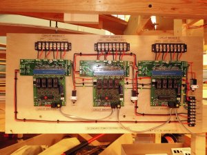
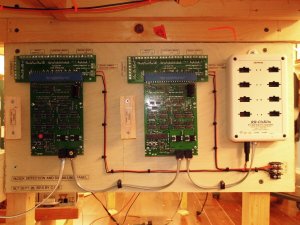
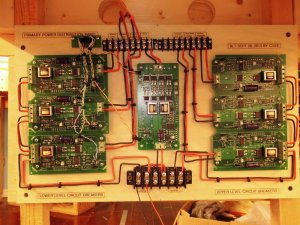
Well Here are the edge connectors in use on my layout. The first picture is 3 PM-42's that I was given I added the edge connectors I mentioned. The second picture is the SE8C's with edge connectors and the RRcirkits TC-64 (block detection).The last one is the PSX circuit breakers used for the majority of the layout. One word of caution about the edge connectors. If you are using 12 guage wire you will have to flatten the ends to be able to fit them in the screw terminals.
Looks good Renegade. I take it those boards aren't actually hooked up to the layout yet.
I thought the distance that wires could be run would restrict the distance. You have all these clustered in one area. What are the dimensions of your layout?
I'm working on it. The PSX breakers are hooked up. Those are older photos. My layout is only 12x 19 three levels. The PM42s were a late addition as I prefer the PSX breakers. The breakers seem to trip without issue. On a layout my size clustering them together is not an issue. I am not particularly a fan of the PM-42 or Bdl168s but the rrcirkits and psx breakers give me the same functionality.
While I am waiting for some components to set up the signaling in section 2, I started some work on the skirting of section 3. A few drywall panels on the lower part of the benchwork. I'll add the Masonite skirting to the upper benchwork that extends further out and will support scenery. The Masonite will extend down far enough to conceal the gap above the drywall.