Sn3: Construction of the Currie and El Dorado

ModelRailroadForums.com is a free Model Railroad Discussion Forum and photo gallery. We cover all scales and sizes of model railroads. Online since 2002, it's one of the oldest and largest model railroad forums on the web. Whether you're a master model railroader or just getting started, you'll find something of interest here.


astroboy

New Member
Last year, on the Whistle Post forums, I started a thread on the Sn3 layout I’m building. That forum has since disappeared. It seems enough time has passed that it’s reasonable to assume that it’s not coming back, so I’m going to more or less reconstruct here, and carry on posting my progress.

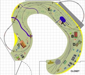
I started a couple of years ago with Anyrail, with Photoshop to fill approximations of scenic features. I tried several narrow gauge scales until I finally settled on Sn3. The latest version of the track plan is below; it has gone through many iterations (this one is 53z_01). The room is about 14 x 10 feet, plus the closet (the grid is 6” squares).

Since this is also my workroom, the table I use is now on casters, and will be stored under the log pond; it’s the gray rectangle sticking out behind the backdrop in the upper right corner. The mainline passes through the backdrop in four places. For ease of access, the goal was to keep the fascia-to-backdrop distance at 30 inches or less. The yellow areas are where that limit was exceeded. The minimum radius is about 27 inches, and the maximum grade about 2 %.

I’m not really that much into operations, but to keep some level of interest along those lines, the following are possibilities: Logs from the flume terminus “A” are transported to the sawmill, “B.” Lumber from the sawmill is shipped to the mining town, “C,” and also used by manufacturers, “D.” Product of the latter are also shipped the mining town, as well as to the interchange, “E.” Trains stop on an irregular basis at the outpost/pack station, “F.”
My room53z_01_sn3.jpg


I’ll be following up with numerous other posts soon.

Jeff
 
Welcome to the forum, Jeff! It looks like your layout is VERY well thought out. I assume you're still in design phase and have not started construction yet - or have you?

I'm excited to watch your progress!


Hello, Chet. I remember you as well, though I must confess I recall your name more than your work!

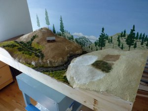
While the track plan was being finalized, I decided to do a test to see how interested I was in building scenery. The result is the partially-constructed diorama you see here. I did just enough to get a taste of a few of the many techniques required.

Diorama05.jpg

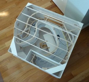
I then built a mockup of the entire room, in 1:6 scale. Here it with the backdrop framing, the track plan, and me hard at work at something or other. The ceiling joists were necessary so that I could plan where the valance/lighting supports would be. It also let me figure out at least a preliminary plan of benchwork, which was helpful due to the irregular shape of the layout.

Mockup_overhead03.jpg

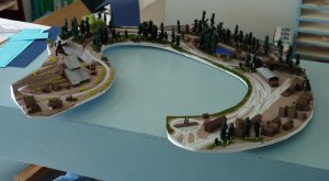
Here is the layout itself, constructed on top of the track plan. With a few exceptions (most notably the stamp mill and the saw mill), all the structures are representations of existing S scale kits.

Mockup_scenery01.jpg

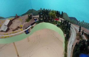
The mockup complete, a train is about to cross the river gorge:

Mockup_scenery02.jpg

The mockup is big enough that my camera fits inside it, so I made a short video tour of the model of the model. I actually learned something from it, too: The main town at the end of the line looked too spread out in comparison to everything else, so in subsequent refinements of the track plan, I compacted it a bit:

[video=youtube;w5-VljR8QN4]https://www.youtube.com/watch?v=w5-VljR8QN4[/video]

Jeff
 
Last edited by a moderator:
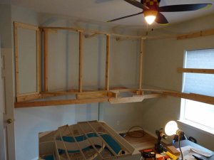
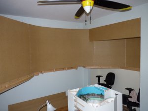
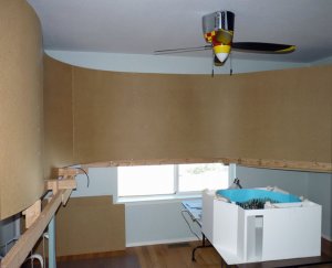
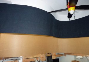
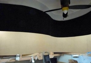
Not much to say about this group of photos. The first shows the backdrop framing; the next two are with the hardboard installed. In all three, the mockup in the foreground is correctly oriented with the room itself.

Backdrop framing01.jpgBackdrop hardboard02.jpgBackdrop hardboard03.jpg


Jeff
 
Looking good Jeff. Liked the video also.

Back in the late 70's when I decided to get out of N scale because of the poor selection of locomotives and the poor running quality of them, I had considered S guage, but back then the availability of S scale was a lot worse than it was today, so I e=went to HO scale. There were a few modelers in HO scale in the area at the time so it did make things a bit easier for the change.

Looking forward to more updates.
 
I don't have the dexterity to work on a model of a model but I can see how that gives you a fairly accurate representation to work with.
 
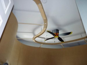
Lighting, Part 1: Hanging this curved rail from the ceiling was the first step; it parallels where the fascia will be. I ended up doubling the number of stabilizing spokes to the backdrop frame. The strip of hardboard on the front edge is for mounting the valance.

valance frame03.jpg
valance frame03.jpg

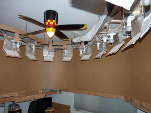
There are 22 LED bulbs altogether. Seven 13-watt bulbs for direct “sunlight,” and fifteen 9-watt bulbs for indirect light, each series on its own switch, with a dimmer for the fill light for a night effect.

Lighting01.jpg

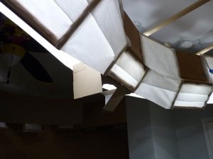
I developed a fairly elaborate system of reflectors, diffusers, and baffles to control the light. In the middle of this shot are the baffles for one of the sunlights.

Lighting03.jpg

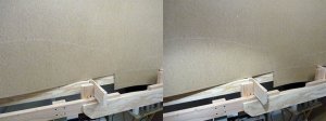
Here’s one reason for the baffles on the sunlights: To keep direct (shadow-casting) light off the backdrop. The chalk line indicates where the 3D scenery will end, and the painted scenery begins. In the second photo, you can see the effect of the baffles at minimizing direct light on the backdrop.

Lighting04+05.jpg


Jeff
 
Last edited by a moderator:


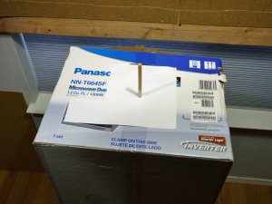
Lighting, Part 2: Another reason for the baffles is to reduce double shadows where two sunlights overlap. I used the simple device shown here to test for double shadows; in this example, the baffles have not yet been optimized for this location.

Lighting06.jpg

To conserve light, the lower portion of the back side of the valance is covered with two layers of bleached muslin, with white poster board higher up. You can also see the “chimneys” I installed to vent heat away from the bulbs.

Lighting07.jpg

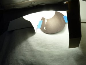
120v LED bulbs aren’t point-sources to begin with; that combined with the white backing on the valance meant the bulbs intended to simulate direct sunlight did not cast sharp shadows at all. To improve upon this somewhat, I mounted circles of black construction paper just opposite the bulbs, on the white poster board.

Lighting09.jpg

Jeff
 
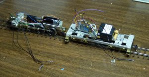
I liked the proportions of the 4-6-0 at the Laws Museum, and, as it happens, a pewter and brass Sn3 kit of it is available from Railmaster. I assembled just enough of it to make it operational:

SP4-6-0_02.jpg

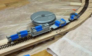
Then I strapped enough weight on it to approximate its final weight. I had a couple of PBL’s car kits, so I mounted the trucks and couplers on their frames, then added enough weight to simulate the two cars, and several more like them:

SP4-6-0_04.jpg

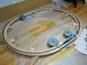
Finally, I put together a test track. The point of this exercise was to test how well the locomotive could negotiate the track plan I had in mind. The nominal 27” minimum radius might in spots dip to about 25”, so I assembled an oval with one curve at 25,” at a 2 % grade. At first I inadvertently had the grade somewhat steeper, and the locomotive had problems, but once I corrected the grade, it made it up just fine:

SP4-6-0_05.jpg

Jeff
 
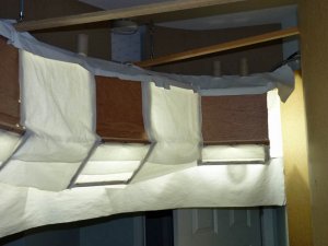
The valance was made from two layers of black denim (one layer wasn’t opaque enough), partially backed by two layers of bleached muslin, as mentioned earlier. The denim was an issue because it had a strong chemical smell to it, which laundering did not remove. Since there was such a lot of it in a confined space, it was imperative to deal with it somehow. In casting about online, I found that someone had hung her new jeans in the sun for three weeks, having read that sunlight (UV?) can cause chemical changes in materials. Well, I tried it, and it worked. After three weeks of hanging outside continuously, I washed the denim once more and the smell was gone.

Since I’m not a tailor, the muslin was attached to the valance with iron-on Velcro, as was the valance to the curved rail to which the lights are mounted. Fusible web—another iron-on product—was used to join the two layers of Velcro, as well as the two layers of muslin. It was also used on any other single edges, as, without a hem, the fabric would have raveled.

The first photo shows how the valance really looks; the second more accurately depicts how it will appear with the layout lighting. I used pieces of lightweight illustration board to fill the gap between the valance and the ceiling.

valance03.jpgvalance04.jpg

Jeff
 
Really nice plan. Wondering about the mill pond, however, wouldn't they have a conveyor going directly into the mill?

I am not from out west so not sure about this, but would make sense.
 
It would, except that the log pond is somewhere along the line between the interchange and the town with the sawmill, and the town is at the end of the line, some miles away. ;-)

Jeff
 
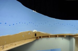
I tried many, MANY techniques and tricks to try to produce a smooth gradation in the sky color, but was never able to obtain consistent results with a reasonable amount of dynamic range, so most of the gradation in the sky is due to attenuation of the lighting (see the earlier posts on lighting). In this shot of the sky, bits of masking tape indicate the approximate top edge of where either clouds, mountains, or trees will be painted. I wanted to get an idea of how big the painted scenery was going to look:

Sky02.jpg

I’d read that one shouldn’t try to paint scenery from memory, and, since I wanted the painted scenery to blend as well as possible with the model scenery, I made up a plan for the backdrop. First, I made a mark at the base of the backdrop every 4 inches, all the way around the room, then measured at each of those points from the base of the backdrop to the top edge of where the model scenery would be(based roughly on the 1:6 scale mock-up). In Photoshop I reproduced the line joining those points in a blank image representing the entire backdrop. The result can be seen as the light brown grid in the image below. I then downloaded photos of mountains, trees, and clouds that looked interesting, and arranged them in that same image, keeping in mind what the modeled scenery in front of the backdrop was going to be like. The image below is a low rez version of that final plan. The idea was not so much to try to reproduce the plan exactly, but to have at least a realistic image to start with, so that I wasn’t just making it up as I went along.

Backdrop design07.jpg

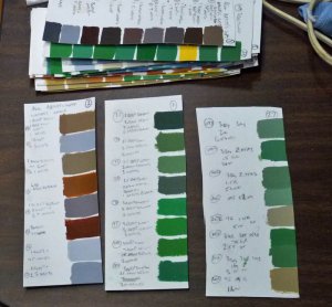
Since I wanted to attempt to match the colors between painted and modeled scenery, as well as shift colors in the backdrop as the distances became greater, I set out to experiment with acrylic paints. For example, I had come up with a good earth color, and made a couple of sample trees that I was happy with, so I matched the bark and foliage colors as best I could, then came up with additional colors to simulate varying distances. What I ended up with was over 200 paint chips(most of which will never be used). Some of these are shown below, each with the proportions of different paint colors recorded next to them on the card. I thought I had covered everything, but it turns out there are still some colors that have to be created, such as ground cover and grass. Of course, I can’t come up with colors of these for the backdrop before I have final samples of the modeled versions.

paint chips01.jpg


Jeff
 
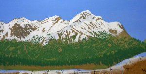
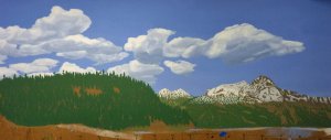
Finally, I started painting the backdrop scenery. I started in November, averaging between an hour and two hours a day, and will likely not finish for at least two or three more months. Below are photos of two of the more successful areas. As you can see, the specter of gradation reared its ugly head again on the clouds. They have a decidedly “paint by number” look which unfortunately is even more apparent in photos than in reality. I’m not sure yet how I’m going to fix that. It isn’t readily apparent, but in the second photo, it’s just possible to just see the log flume contouring along the foreground hill, near its base. The terminus of the flume will be modeled to the left of this hill, and somehow it will disappear around a bend, to then reappear in the distance on the backdrop.

Backdrop painting05.jpgBackdrop painting06.jpg


Jeff


I don't think they're that bad -- some 3-D trees just in front of the backdrop will probably smooth things out very well.


Affiliate Disclosure: We may receive a commision from some of the links and ads shown on this website (Learn More Here)

Back
Top