New 9'x5' HO Layout

ModelRailroadForums.com is a free Model Railroad Discussion Forum and photo gallery. We cover all scales and sizes of model railroads. Online since 2002, it's one of the oldest and largest model railroad forums on the web. Whether you're a master model railroader or just getting started, you'll find something of interest here.


Thanks for posting, I think I will go with a smaller water body on mine.. Thanks for the tip on the paint you are buying.

I wonder where/what you used for the water? Was it from the hardware store or hobby store? lasm
 
We used Woodland Scenics' simulated water solution. It comes ready to use in a 16 oz bottle for anywhere between $17-22/bottle. Most hobby shops have it, but I doubt any hardware stores would. You can see the size of our water feature and ours took one bottle per "coat"...two total. Pretty good stuff and looks very realistic once cured.
 
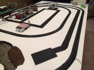
Since the river is complete, we've moved on to the streets and roads. I masked off the roads with painters tape, then gave them two coats of paint to simulate asphalt. Again, the paint I used was a mistint from a local paint store and picked up very inexpensively. Surprisingly, there was a lot of paint bleed through on the foam from under the painters tape. Despite that, we’ll be fine as all of the foam right up to the road will be painted the base brown, then covered with the landscaping grass. In the end, you shouldn’t be able to tell because it will be covered.

Layout20.jpg
​


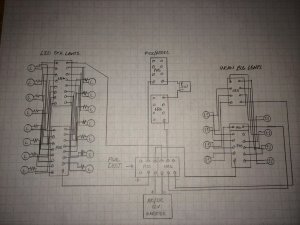
After going through things again, I redesigned the electrical part of our layout. Originally, we were going to group our LED street lights into groups of three with one resistor per group. Now, we’re going to wire them individually with one resistor per lamp. I’ve also reworked the power distribution block as well as the incandescent building lights to make things a little easier than the earlier plan. As you can see, we will have room for at least four additional building lights as we expand our city center. Or, we can use that extra space for other 12V powered features.

Layout22.jpg.jpg


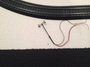
Here, you can see one of our LED street lamps. There will be a total of 15 of these throughout our layout. The dot shown close to the road is the mounting point. Since we want both LED's to light together, both red wires will be soldered together with a resistor for the positive lead.

Layout21.jpg

​
 
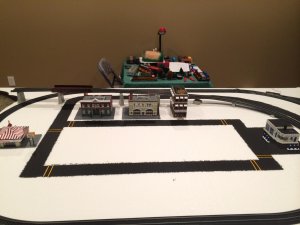
Here, we have painted the parking lot area and the cross walks in the city center. Luckily, I had some yellow modeling paint that worked perfectly. This view provides a nice view of the river as well. One dilemma I’m having is where to locate the gravel pit. I’ve bounced back and forth between the back right corner near the elevator and just behind the parking lot near the river. At this point, I’m leaning towards doing a gravel road off the asphalt road near the parking lot and locating it there.

Layout23.jpg


Layout24.jpg


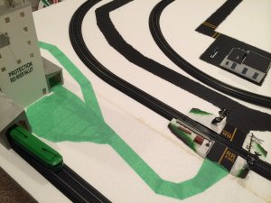
This is a closeup photo of the elevator area. My plan is to build a gravel road right after the crossing in the taped off sections. Grass will be placed in the bare white sections of foam. After the grass is put down, I’ll peel back the tape, paint that area, the sprinkle gravel there for a relatively authentic look. If we locate the gravel pit near the parking lot, I’ll repeat a similar series of steps over there.

Layout25.jpg
​
 
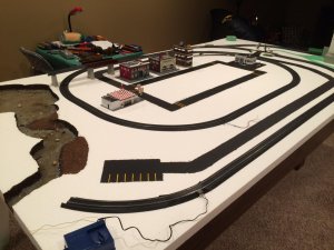
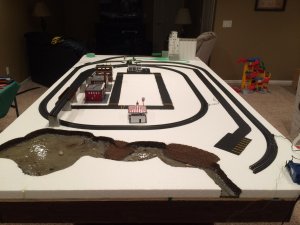
This is a wide shot of our layout so far. There are a few little nit pick things to do yet, such as masking off the gravel road near the parking lot for the gravel pit and deciding what I’m going to do with the pier that will be located in the river and get it built. I will also need to finalize building locations and get that marked on the foam.After all of that is done, I will begin the wiring process using the diagram shown earlier.

Because of the limited underside access due to the pool table, I will build a set of legs and raise one side up to do my drilling and wiring, then proceed to the other side as I don’t want to drill through the table itself. Then, I will begin wiring things to together and complete that process.
I’m undecided as to where to locate the distribution blocks. They won’t be going under the board due to access limitations, and will probably to towards the back. That should limit visibility problems and still allow access in case something needs to be changed. Wiring the layout will be a work in progress.

Layout26.jpg
​
 
Fantastic post!!!

I really enjoyed reading it, thank you!

One thing I ask, could you make the font a bit bigger? My eyes are not what they use to be, neither is anything else, but that is another story all together.
 
It's been a while since I last posted an update, so wanted to do that tonight. Basically, I'm still in wiring mode and will be for a little while longer. About half of the "fixtures" in the layout are wired to the barrier strips, but are not connected. I'll finish running all of the wires before doing that. I'll also need to solder all of the fixtures as well.
Layout28.jpg
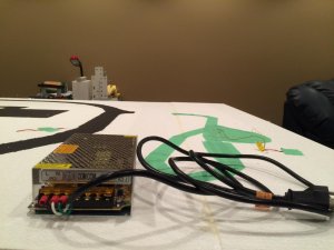
Here's a little gem I picked up cheap on eBay. It's a 12v 10a transformer that'll power our layout nicely. I've tested it to be working and have adjusted the voltage to right at 12v. It was only $15 shipped, much less than a lot of the other options I had seen out there.
Layout29.jpg
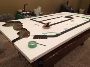
This is a broad view of our layout during the wiring process. I was concerned about access due to the pool table under the layout and I was right: it has presented some challenges. What I've done is to prop up the train table with a 1x4" which is just enough room to reach under and pull wires. It also allows for enough clearance that I'm not going to drill into the pool table itself as I'm making the holes.
Layout30.jpg
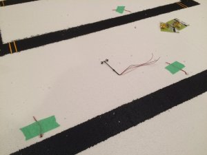
As I pull wires, I'm taping them off as we go. That prevents the wiring from being pulled down through the hole. Once all of the wires are run, I'll begin soldering all of the fixtures and connecting them on the barrier strips.
Layout31.jpg
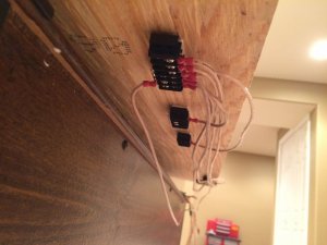
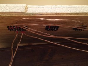
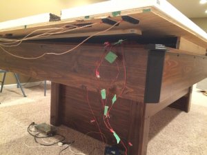
Here's a view of the underside of our layout. You can see the barrier strips are already wired from the master power block. You can also see the wires that have already been run. I'm labeling them as either a street light or building light so I know which barrier strip they belong to when we get to the connecting phase.

Incidentially, I'm using phone wire to run to the fixtures and 14ga speaker wire to run between barrier strips. It's what I had on hand and seems to be doing a nice job. Guess we'll see exactly how good once things are wired and the switch is turned on.

 
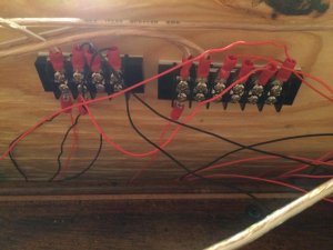
Final update for the evening. Here, you can see the barrier strips and some of the fixture wiring in the back ground. The first block is the main power distribution block. The next two are for accessories like track switches. In the distance there are four more strips, which are for the buildings and street lamps.

Layout32.jpg

I probably have another two nights running wires before moving on to soldering the fixtures and connecting things to the barrier strips. Once all of that's done and tested, I'll move on to building hills and mountains and get started on our other landscaping.

Even though our layout is relatively small compared to most on the forum, building it has been very rewarding so far. Our son has taken a very keen interest in helping me and is spending many of his evenings with me, right by my side helping out. He (and I) can't wait until a lot of this "behind the scenes" work is done so we can start on the landscaping and making it look good. As always, thanks for keeping up with us...any feedback or suggestions are welcomed.


Your son will probably be well suited to electrical engineering if he soaks up any of your knowledge!! Your job is first class and you really got a good deal on that transformer.

Thanks for posting--lasm
 
The last week has been spent basically running wires to all of the street and building lights. Couldn't believe it, but we ended up using about 180' of wire once things were said and done. This seems to be the most tedious part of the build, since you really can't see anything is being done scenery wise. Here are a few pictures of what we've been doing...

First, I finished wiring the master power distribution barrier strip...
Layout33.jpg

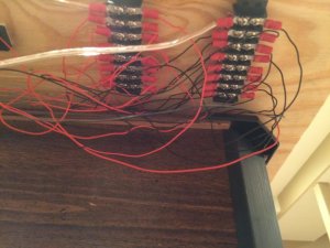
Then, I connected each set of building light wires to the appropriate barrier strip...
Layout34.jpg

Then, I finished wiring each street lamp up...
Layout35.jpg

After all of our electrical elements are wired and tested working, I'll finish by cleaning up the wiring so it looks as pretty as it works. Many hours just in this part alone!
 
Our six year old stayed up well past his bed time tonight, begging me to get one of our street lamps lit. Being a spoiled little boy, he got his wish...imagine that!

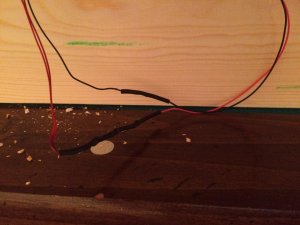
Although I didn't get a picture until the soldering was done, each LED street lamp requires a 500 +/- ohm resistor be soldered in. I've chosen to run mine on the positive side of things, but they can be on the negative side as well. Once the soldering and heat shrink was done, I pushed the wiring through the foam and underlayment and positioned the street lamp into place.
Layout36.jpg

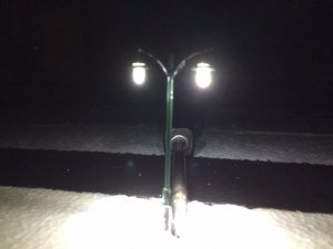
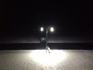
Even though it's being held in place by a screwdriver, you'll get a very good idea what the lamps will look like once installed for good. They're very bright and will light things up well when the over head lights are off. Here's a close up view of the lamp...
Layout37.jpg

Final picture for the night: a broader view of the street light. We'll have a total of 15 of these on our 9'x5' layout...plus building lights. It'll take hours more to solder these and the building lights all up before moving on to more interesting things like scenery. So far, so good!
Layout38.jpg
 
Last edited by a moderator:
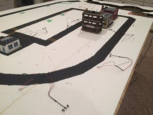
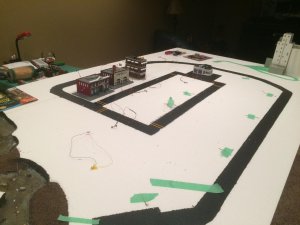
I suppose everyone that runs lighting in their layout goes through this...the tedious job of running wire, soldering and connecting. Happy to report that we can see the light at the end of the tunnel and that our wiring is about 75% done. One more building to wire and seven more street lights and we can put this part of the build to rest. Our son is starting to ask when he can start running engines again, which is a little ways down the road. After wiring will come the scenery and it'll look like we're actually doing something. In the meantime, two pictures of our messy layout...

Layout40.jpg

Layout39.jpg
 
Your messy is actually pretty darn neat!! Looking forward to seeing your scenery, too. Thanks for posting, lasm


Affiliate Disclosure: We may receive a commision from some of the links and ads shown on this website (Learn More Here)

Back
Top