View attachment 43506
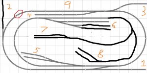
Here's what I've came up with so far. There's a 50 peice limit to the trial version of Anyrail so I loosely drew in what was left ha ha.
1. This is where the mainline starts for bigger Class 1 railroad. The mainline includes the whole outer loop. I could put a staging yard beyond here.
2. Here is where if I expanded in the future I would put a large industry being served by the Class 1 railroad.
3. This is where the Class 1 mainline branches off from the short line. Could put another staging yard beyond here.
4. An interchange siding. I would move the turnout to the other side of the siding, due to directions.
5. Sawmill
6. Small yard
7. Logging camp.
8. Miscellaneous industry. Haven't decided what yet.
9. I could put a passenger station, road, or random scenery here.
If you can see close enough the track in the red circle isn't connected. How would I make sure the lengths and curve degrees are all correct so that the track would connect?
This is a very rough draft so let me know of any mistakes I've made.
**>
Hi BNSF Nut, I'm Trussrod on here but David is my name and been involved in the hobby for the last 63 years.
Welcome to the forum and glad to see your asking a variety of questions, to not only try and determine what you want to do 'but' also what is possible and will actually fit in the area you have to work with, look realistic and operate as you expect.
1st off, building any layout in a room that takes on moisture to any extent is not a good idea unless you have a dehumidifier and even that may not be enough to prevent problems? Just changes in temperature of a room, if too great can cause problems unless you take steps to prevent the expansion and contraction problem of your track work.
It's been mentioned prior about about track buckling due to expansion expansion and problems with contraction. If you use flex track or even sectional track, such as Atlas or others, a simple solution is just don't solder every other three foot section to the next one and be sure to leave about a 1/16th inch gap between the to adjoining sections so they can slip back and forth to compensate as the changes require. I assume track like Bachmann etc uses something similiar but working with flex track allows for more flexibility but you also need to watch your spacing of tracks being too close to each other even if on cork road bed especially on curves but also in sidings as things can get very tight if your not cautious.
My suggestion for a your layout bench work, is I believe, more what you were thinking of if you have a corner or a room to work with for an 'L' shape or maybe even a 'U' shape with a loop on either end so if you want to watch a train run for a bit you can. That's the way mine is laid out but it a folded, loops over itself at one location, dog bone or basically loop-to-loop. This can still be operated as a Point-to-Point without any continuous run such as a delivery and the empty pick-up possibly being delivered on down the line to another location or even taken back to where the loaded car came from. My suggestion, would be to take two 4x8 sheets of plywood or OSB chipboard and cut one in half so you have two 4x4 end pieces for the two loops on either end and cut the other sheet down the middle so you have two sections of 2' x 8' that can be butt together in a corner with a 45* corner piece to allow for the inner curve. The 8' length of these two sections can of course be adjusted shorter
as needed. This does several things. It makes for a layout that can for the most part easy to reach most things as your depth isn't so great, it's a lot more pleasing to operate on as you can watch your trains making both right hand and left hand curves without seeing it go around the same oval. It like it's going to new territory as it spread thing out more.
Now in looking at your layout plan above several things come to mind from all my past experience. First off, you haven't mentioned what gauge your intending to model, unless I've missed it? Is it HO gauge, and what is your prefference, steam or diesel? If it HO and your going to stick with the plan above you'll need to run the smaller Loco's due to the much tigher radiuses as the larger ones very probably won't even go around them as is the case with even some steam loco's that have three and four flanged drivers as they will bind on the tighter curves!
Keep one thing in mind, even using these cad programs it all too easy to fit things in thinking they will work but when you actually get to laying your track you'll find the spacing is just way too tight. In HO you will need to leave at least
As is your plan has some inner radiuses that only an small to axel diesel or an 0-4-0 steam engine would run around. It's very easy for the mind to preceive something that we think will work and fit till we get to actually laying rail. An NMRA HO clearance gauge is 2" wide and it best to allow at least an extra 3/4" clearance bare bare minimum on straight tracks and probably at least 1.25 to.50" on curves if your going to have any double main line situations. In fact if you use some of the preformed roadbed and track they probably won't allow you to fit in as much as you've got. Again I'm think your working in HO.
As your plan is drawn even the larger outside oval just has barely an 18" radius which is generally considered as a minimum. There is no way your going to run anything but very small loco's and very short cars on it. Again if your in HO. If your in N gauge then it an entirely different story as it should work fine.
I have a number of pictures showing how I built my bench work and the L gurder construction which is very useful if you want any changes in elevation although Woodland Scenics does offer a very complete selection of foam Sub-Terainian risers etc if you would rather just work from a flat surface.
I'm a dealer for Woodland Scenic and have their complete selection available as well as having the complete line of NCE products. I also have Atlas & Peco track and turnouts available as well as Bachmann etc.
Let me know if I can be of help to you? My contact info is at the bottom of my signature below.




 There is actually a really good version of #28 that was expanded to 6x11 I think. It is in a book that I do not keep at every desk so I can't check. I believe it used 24" radius curves. I've always wanted to build it. Considering your first drawing I thought you would like #25. Ditch the turn table/round house and make Schmidt's switch more useful in that area. Definitely an "urban" industrial layout though.