Lionel 224 steam engine, questions on motor and tender

ModelRailroadForums.com is a free Model Railroad Discussion Forum and photo gallery. We cover all scales and sizes of model railroads. Online since 2002, it's one of the oldest and largest model railroad forums on the web. Whether you're a master model railroader or just getting started, you'll find something of interest here.


Blk6999

New Member
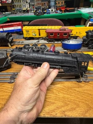
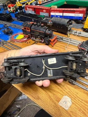
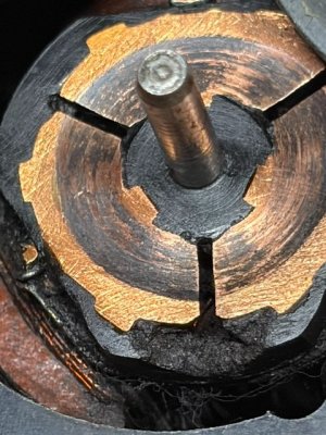
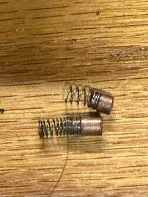
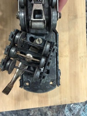
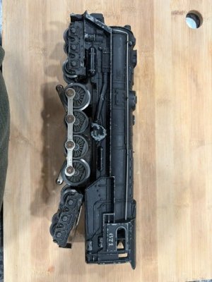
Hello, got my Dads old 224 out this past weekend. One of my favorite post war engines in my collection. It was not running well so took it appart to clean. During my cleaning noticed the copper plate on top of the armature was caved in. Where the brushes touch, could fee a little indentation. None of my other post war engines have shown this much wear, see pictures. This concerned me. Visited Trainz online and ordered new brushes and springs (motor had two different sized springs in it). Checked if they had any spare parts for the engine, they has (1) armature, went ahead and got that too. Should be coming in a week. Have a few questions appreachate any guideance.

1) Does my current armenture look that bad? Thinking I will wait till the new one arrives and use the best of the two. Is this amount of wear common? How much run time is require to wear in this much?

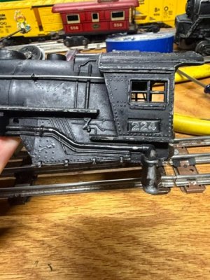
2) My engine has a engine number plate vs ink stamped numbers. Was this a O gauge thing vs O-27? This may be my only O gauge Post War Steamer, rest are O27.

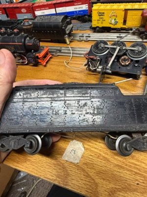
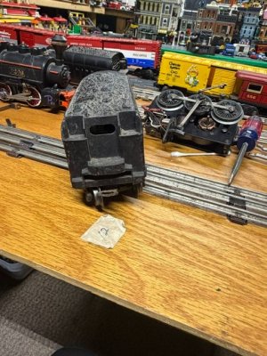
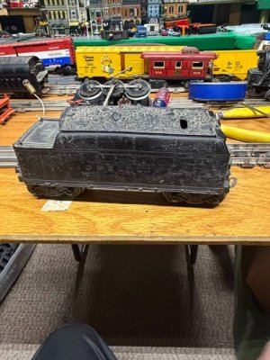
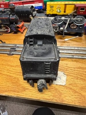
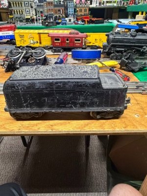
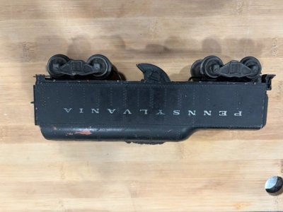
3) My tender looks horrable, like someone dragged it thru gravel. The Lionel lines branding is visable but no color in the letters. Almost looks like it had been painted black. Question, is this the correct tender for my 224? looking at the internet looks like a 2466W, but the 671W and 2020W look basically the same. How do you tell the differnce between the 3. Mine has a whistle in it. Was the $55 my father paid for the engine and tender 30 years ago a fair prices? Guessing condition was similar to as is today. He tended to purchase engines that were well loved vs shelf queens.

4) If I wanted to strip the tender and repaint (believe already painted) what stripper would be safe for the plastic (body plastic) and what paint is closest to orginal. Not planning on painting the engine as looks orginal.

Parden my mess on my layout and number of pictures.
 

Attachments

  • IMG_4370.jpeg
    IMG_4370.jpeg
    88.9 KB · Views: 28
  • IMG_4369.jpeg
    IMG_4369.jpeg
    99.4 KB · Views: 26
  • IMG_4368.jpeg
    IMG_4368.jpeg
    95.1 KB · Views: 25
  • IMG_4367.jpeg
    IMG_4367.jpeg
    102.2 KB · Views: 23
  • IMG_4366.jpeg
    IMG_4366.jpeg
    89.8 KB · Views: 28
  • IMG_4365.jpeg
    IMG_4365.jpeg
    89.3 KB · Views: 23
  • IMG_4364.jpeg
    IMG_4364.jpeg
    91.9 KB · Views: 26
  • IMG_4363.jpeg
    IMG_4363.jpeg
    91.2 KB · Views: 32
  • IMG_4361.jpeg
    IMG_4361.jpeg
    69 KB · Views: 29
  • IMG_4371.jpeg
    IMG_4371.jpeg
    85.5 KB · Views: 29
Last edited:
Thank you for sharing a beautiful old piece of Lionel history.

I’m by no means an expert on post-war locomotives, and certainly not on pre-war tenders. I believe your 2466W tender is a 1945 prewar carryover, possibly a pre-war 1938-1942 tender.

1. Armature wear - not uncommon for a well-used locomotive. How much run time - a lot of hours, probably hundreds.

From your close‑ups, the copper commutator plate shows normal wear for a motor that’s seen decades of use. That slight indentation where the brushes ride is caused by countless hours of contact and heat cycles. It’s not catastrophic, but it does mean the brush seating surface is uneven, which can cause erratic running or sparking.

What I would do: If the new armature from Trainz arrives in good shape, use it. If the new one looks worse or has uneven segments, keep your original and polish the commutator lightly with 600–800‑grit paper, then clean the slots with a toothpick or X‑Acto blade. Replace both brushes and springs together; mismatched tension can cause uneven wear. That kind of indentation usually takes hundreds of hours of run time, but it’s not unusual for a postwar motor.


2. Number plate vs. ink stamp - The metal number plate on your 224 cab means it’s an O‑gauge model, not O‑27. Lionel used plates on the higher‑end O‑gauge engines (like the 224, 225E, 226E) and ink stamps on the smaller O‑27 line (like the 2035, 2026).


3. Tender identification - Your tender looks like a 2466W; which is the correct whistle tender for the 224.

Here’s how to tell them apart:
TenderWhistleLetteringTrucksEra
2466WYesEmbossed “Lionel Lines”4‑wheel1938–42
671WYesWhite stamped lettering6‑wheel1946–49
2020WYesWhite stamped lettering6‑wheel1946–49
The embossed lettering and 4‑wheel trucks confirm it’s the 2466W. The rough finish you see is likely repainted black over the original semi‑gloss; common for engines that were “well loved.” And yes, $55 - 30 years ago was a fair price for a running example in that condition. Today, even worn ones can fetch even higher values depending on completeness.

I believe your 2466W tender is a prewar carryover, possibly even a pre-war tender. Lionel didn’t design a brand‑new tender for the 224 in 1945. Instead, they reused the prewar 2466W tooling from 1938–1942 and any leftover stock from the pre-war era. That’s why your tender has: Embossed “Lionel Lines” lettering (prewar style) 4‑wheel trucks (prewar style) Heavier die‑cast construction. Whistle unit (added late prewar, continued postwar) In 1946, Lionel switched to the 2466WX, which had extra railings and a slightly more “postwar” look.

The 224 and 2466W combination was sold in sets from 1939–1942. When Lionel resumed production in 1946, they updated the design but kept the same general look. Your set bridges the prewar and postwar eras, a great piece of transition history.


4. Stripping and repainting the tender - There are several real experts on this forum, I'm not one of them.

If you decide to refinish it: Safe stripper for Bakelite or early plastic: Use 91% isopropyl alcohol or Citristrip; both gentle on Lionel’s early plastics. Avoid acetone or lacquer thinner; they’ll melt the shell.

Paint recommendation: Rust‑Oleum Satin Black or Tamiya TS‑29 Semi‑Gloss Black are close to the original Lionel finish. Apply light coats and let cure fully before reassembling. Re‑lettering can be done with dry transfers or water‑slide decals if you want to restore the “Lionel Lines” look.


My final thoughts - Your 224 is a gem! Heavy die‑cast and built like a tank. With a fresh armature, new brushes, and a cleaned commutator, it’ll run like it did in the 1940s. That tender may look rough now, but it’s the right match and worth keeping original if possible


Thank you again for sharing it with us.
 
Last edited:


Thank you for sharing a beautiful old piece of Lionel history.

I’m by no means an expert on post-war locomotives, and certainly not on pre-war tenders. I believe your 2466W tender is a 1945 prewar carryover, possibly a pre-war 1938-1942 tender.

1. Armature wear - not uncommon for a well-used locomotive. How much run time - a lot of hours, probably hundreds.

From your close‑ups, the copper commutator plate shows normal wear for a motor that’s seen decades of use. That slight indentation where the brushes ride is caused by countless hours of contact and heat cycles. It’s not catastrophic, but it does mean the brush seating surface is uneven, which can cause erratic running or sparking.

What I would do: If the new armature from Trainz arrives in good shape, use it. If the new one looks worse or has uneven segments, keep your original and polish the commutator lightly with 600–800‑grit paper, then clean the slots with a toothpick or X‑Acto blade. Replace both brushes and springs together; mismatched tension can cause uneven wear. That kind of indentation usually takes hundreds of hours of run time, but it’s not unusual for a postwar motor.


2. Number plate vs. ink stamp - The metal number plate on your 224 cab means it’s an O‑gauge model, not O‑27. Lionel used plates on the higher‑end O‑gauge engines (like the 224, 225E, 226E) and ink stamps on the smaller O‑27 line (like the 2035, 2026).


3. Tender identification - Your tender looks like a 2466W; which is the correct whistle tender for the 224.

Here’s how to tell them apart:
TenderWhistleLetteringTrucksEra
2466WYesEmbossed “Lionel Lines”4‑wheel1938–42
671WYesWhite stamped lettering6‑wheel1946–49
2020WYesWhite stamped lettering6‑wheel1946–49
The embossed lettering and 4‑wheel trucks confirm it’s the 2466W. The rough finish you see is likely repainted black over the original semi‑gloss; common for engines that were “well loved.” And yes, $55 - 30 years ago was a fair price for a running example in that condition. Today, even worn ones can fetch even higher values depending on completeness.

I believe your 2466W tender is a prewar carryover, possibly even a pre-war tender. Lionel didn’t design a brand‑new tender for the 224 in 1945. Instead, they reused the prewar 2466W tooling from 1938–1942 and any leftover stock from the pre-war era. That’s why your tender has: Embossed “Lionel Lines” lettering (prewar style) 4‑wheel trucks (prewar style) Heavier die‑cast construction. Whistle unit (added late prewar, continued postwar) In 1946, Lionel switched to the 2466WX, which had extra railings and a slightly more “postwar” look.

The 224 and 2466W combination was sold in sets from 1939–1942. When Lionel resumed production in 1946, they updated the design but kept the same general look. Your set bridges the prewar and postwar eras, a great piece of transition history.


4. Stripping and repainting the tender - There are several real experts on this forum, I'm not one of them.

If you decide to refinish it: Safe stripper for Bakelite or early plastic: Use 91% isopropyl alcohol or Citristrip; both gentle on Lionel’s early plastics. Avoid acetone or lacquer thinner; they’ll melt the shell.

Paint recommendation: Rust‑Oleum Satin Black or Tamiya TS‑29 Semi‑Gloss Black are close to the original Lionel finish. Apply light coats and let cure fully before reassembling. Re‑lettering can be done with dry transfers or water‑slide decals if you want to restore the “Lionel Lines” look.


My final thoughts - Your 224 is a gem! Heavy die‑cast and built like a tank. With a fresh armature, new brushes, and a cleaned commutator, it’ll run like it did in the 1940s. That tender may look rough now, but it’s the right match and worth keeping original if possible


Thank you again for sharing it with us.
Brutte,

Thank you for putting so much detail in your response. There is something a little magical about these old steam engines. Regarding the armature, will attempt to sand down the commutator as you suggest. Not sure how much copper is left, will be gental. Would rather have the engine run rough then not at all.

Regarding the tender, I thought it was a 2466W also. Looks great with the 244. Regarding stripping the paint, wish I could remove the repaint and leave the orginal. Concerned any stripper will take away some of the detail. Also a perfectly painted tender may look odd behind my orgjnal (chipped up) engine. Will test your suggestion on a non noticable area of the tender before moving forward

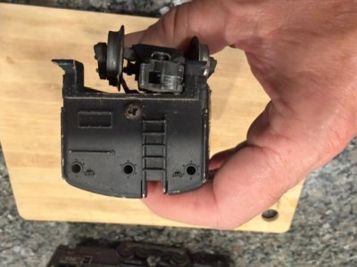
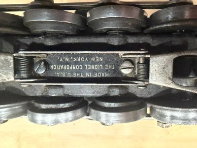
Regarding the number plate, didn't know the O gauge engines recieved the plates and O27 the stamps. In my collection I do 671 engine. With the 8 drive wheels assumed it was also O gauge. It has a stamped number on the side of its cab. Hard to believe it would run on o27 curves, I am running it on O42. There are two holes drilled out on the floor of the cab (at the sides), would you happin to know what they were for? Picture attached. Assuming part of the casting process but my engine is old and well loved could be missing some stuff. I believe this tender 2671W is correct for the 671. It has the 3 holes stamped out in the rear, someday hope to install red light there. Aware may affect its value, do not plan on ever parting with it. Pictures are upsidedown, don't know how to spin them around.
 

Attachments

  • IMG_4375.jpeg
    IMG_4375.jpeg
    66.7 KB · Views: 18
  • IMG_4378.jpeg
    IMG_4378.jpeg
    52.4 KB · Views: 16
  • IMG_4377.jpeg
    IMG_4377.jpeg
    49.1 KB · Views: 19
  • IMG_4376.jpeg
    IMG_4376.jpeg
    73.5 KB · Views: 19
  • IMG_4374.jpeg
    IMG_4374.jpeg
    62.4 KB · Views: 20
Aware may affect its value
If I were you, I would not worry about value. Leaving it the way it is cosmetically is not a problem either. What really matters is that it makes you happy.

One of the first pieces of advice I received when my obsession with Lionel trains began. Buy what you love, not for its value as a collectible. I think that logic applies here.
Regarding the number plate, didn't know the O gauge engines recieved the plates and O27 the stamps. In my collection I do 671 engine. With the 8 drive wheels assumed it was also O gauge. It has a stamped number on the side of its cab. Hard to believe it would run on o27 curves, I am running it on O42.
While I am not an expert I have seen enough from Lionel to know that no "rule" is set in stone, there seems to be an exception to them all. The 671 was designed for O‑gauge operation, but it can handle O‑27 curves if the track is laid perfectly, though, as you noticed, it looks and runs better on O‑42.

Those two holes drilled in the cab floor of your Lionel 671 are almost certainly factory features. On the postwar 671 (and its close cousin, the 2020 turbine), Lionel cast those holes to accommodate mounting screws for the smoke unit bracket and sometimes for wire routing from the headlight or smoke element. They weren’t meant to hold visible parts, so if your locomotive’s wiring or smoke assembly was serviced over the years, the holes might look empty.

The 2671W tender is indeed correct for that engine. The three stamped holes in the rear were for the optional backup light lens and housing that Lionel added on later versions. Installing a red light there would be a perfect period‑style upgrade.

Your engine being “old and well loved” makes it even better, those little quirks are a part of its story.
Pictures are upsidedown, don't know how to spin them around.
You're not the first, and you won't be the last forum member to deal with that, but unfortunately, I can't help with it.
 
Hello Folks,

Sorry I'm a little late to the party, but with Bruette's excellent write-up and the video posted by Marlin39, virtually all of Blk6999's questions were very well answered without my help. Which was definitely a good thing! 😁

It just so happened that I had a non-running Lionel 1655 Scout waiting in the wings for a good tear-down, cleaning, and refurbishing. I finally got it tore apart late last evening and let the armature soak overnight in mineral spirits to degrease and degunk it. Mineral spirits or contact cleaners are safe to use, I wouldn't trust much else for cleaning and degunking. DON'T use alcohol, as I have heard it can dissolve the enamel coating on the winding wires, which would be a bad thing (can you say "short-circuit"?:eek:). I thought I'd show a method that I have developed within the last year or so for cleaning AND refurbishing the commutator faces on armatures. The armatures have to be removed from the motor frames, however. Haven't quite figured out (yet) how to do them while they're still in the frames! 🤔

Within the past year or so, I've done a handful of loco motor armatures and even a few whistle motor armatures. It merely involves chucking the armature up in a drill press, and wet-sanding the commutator faces with a small variety of wet-or-dry sandpaper where smaller, cut-to-size sheets have been glued to blocks of wood. Although previously done on my bench top drill press, I got to wondering if a hand drill would work just as well. Figuring that most hobbyists would stand a far better chance of owning a hand drill than they would a drill press, I decided to try my cordless drill on this latest armature. And I think it ended up working pretty good. Let's take a look.............

20241030.JPG

Here we have my armature chucked up in my cordless drill. The commutator face is pretty filthy and slightly scored, so probably about average. I have cut out and glued some wet-or-dry sand paper to both sides of a couple of blocks of wood (1x2's). 320 grit on one side, and 400 grit on the opposite side of one block, and 800 grit/2000 grit to the other block. Labeled of course, so I know which grit is which. No rhyme or reason for the grits, they were just what I found handy when digging thru my sandpaper scrap pile. However, if you have a supply of 240/320/400/600 grits, these should be more than adequate for any commutator sanding jobs, I would think. Also a green scouring pad, and a spray bottle of water rounds out what I generally use.


20241031.JPG

I started out by wetting down the 320 grit paper, and sliding the block along the commutator while spinning the armature in the drill. It took several passes of the block to get the face cleaned up good. Keep the block square and flat against the commutator face while sanding. Stop frequently and wet the paper down, and wipe the commutator off to keep the sandpaper clean of the sanding residue. This picture shows the commutator face when I finally got it to my liking with the 320 grit.


20241032.JPG

I also held the green scouring pad to the outside of the spinning armature, to help clean up the metal winding plates, and also against the armature shaft for the same reason. Not totally necessary, but heck, since it only takes a few seconds, you might as well. I've also noticed a small fiber washer that fits on the shaft on virtually every armature I've worked on, so be sure and remove it first so you don't lose it. I had already removed it in this, and the previous, picture.


20241033.JPG

And here is the finished armature, after advancing through the finer and finer grits of sandpaper. Here you can see the 400 and 2000 grits that are on the opposite sides of the blocks. Also notice, a little copper residue on the 2000 grit paper. I probably pressed the board a little too hard against the commutator face while not keeping the paper wet enough. If I can't get the paper clean, I may want to strip this side off and glue a new strip of sandpaper back on.


20241034.JPG

And here's a closer view of the commutator. The fiber washer has been slid back on the shaft, and you can see the reflection of the shaft in the polished commutator surface. Don't forget to clean the grooves out between the commutator segments. In most cases, I have found that blasting the grooves out with some compressed air works just fine. Although the commutator face ain't mirror-perfect, it's clearly much cleaner and much smoother that what it started out at.

In conclusion, I'd have to say the hand drill idea worked out pretty good. However, I think the process is a little faster and easier with a drill press, so I will continue to do my future armatures with mine. Home hobbyists lacking a drill press should be able to achieve satisfactory results with a hand drill too, just take it slow and easy for best results.

I would like to think that the commutator faces would stay clean and shiny after putting the motors back into service, but this tends not to be the case. The commutator faces still get dirty, most likely from the black carbon that the brushes are made from, so occasional cleanings will still be necessary. However, with a nice, finely polished face, the brushes should last much longer. At least I would think they would.

And finally, all my motors that I have done this to have ran just fine thus far. Hopefully they will for years to come. Haven't managed to mess up anything yet! 😬🤪
 
That looks like a great way to clean the commitator. Thank you for sharing.

I cleaned the armuture the best I could while still in the motor frame. Used 1000 grit sandpaper and the communtor looks better, not perfect. After installing the springs and brushes the motor will not work. I can see the armature trying to turn, just moves a few degress and stops. I have attempted to spin the wheels hoping the kentic energy would help the motor keep spinning, no luck. Have tested the engine on the tracks and on my bench (bring hot and neutral wires directly to the brushes). Wondering if some of the copper dust I was filing got into the amature causing the issues.

Next step I believe would like to take the armature out of the motor block but one of the drive wheels and the center wheel require removal. I attepted to knock out the axle of the drive wheel without the gears with no luck. What is the proper procedure for removing the drive and center wheels. I do not plan on taking the motor block appart as is rivited and that looks like a pain drilling out and then getting back togather.

Unfortunately the video did not remove the drive wheel (remove the armature from motor block).
 
Hello Folks,

Sorry I'm a little late to the party, but with Bruette's excellent write-up and the video posted by Marlin39, virtually all of Blk6999's questions were very well answered without my help. Which was definitely a good thing! 😁

It just so happened that I had a non-running Lionel 1655 Scout waiting in the wings for a good tear-down, cleaning, and refurbishing. I finally got it tore apart late last evening and let the armature soak overnight in mineral spirits to degrease and degunk it. Mineral spirits or contact cleaners are safe to use, I wouldn't trust much else for cleaning and degunking. DON'T use alcohol, as I have heard it can dissolve the enamel coating on the winding wires, which would be a bad thing (can you say "short-circuit"?:eek:). I thought I'd show a method that I have developed within the last year or so for cleaning AND refurbishing the commutator faces on armatures. The armatures have to be removed from the motor frames, however. Haven't quite figured out (yet) how to do them while they're still in the frames! 🤔

Within the past year or so, I've done a handful of loco motor armatures and even a few whistle motor armatures. It merely involves chucking the armature up in a drill press, and wet-sanding the commutator faces with a small variety of wet-or-dry sandpaper where smaller, cut-to-size sheets have been glued to blocks of wood. Although previously done on my bench top drill press, I got to wondering if a hand drill would work just as well. Figuring that most hobbyists would stand a far better chance of owning a hand drill than they would a drill press, I decided to try my cordless drill on this latest armature. And I think it ended up working pretty good. Let's take a look.............

View attachment 271580
Here we have my armature chucked up in my cordless drill. The commutator face is pretty filthy and slightly scored, so probably about average. I have cut out and glued some wet-or-dry sand paper to both sides of a couple of blocks of wood (1x2's). 320 grit on one side, and 400 grit on the opposite side of one block, and 800 grit/2000 grit to the other block. Labeled of course, so I know which grit is which. No rhyme or reason for the grits, they were just what I found handy when digging thru my sandpaper scrap pile. However, if you have a supply of 240/320/400/600 grits, these should be more than adequate for any commutator sanding jobs, I would think. Also a green scouring pad, and a spray bottle of water rounds out what I generally use.


View attachment 271581
I started out by wetting down the 320 grit paper, and sliding the block along the commutator while spinning the armature in the drill. It took several passes of the block to get the face cleaned up good. Keep the block square and flat against the commutator face while sanding. Stop frequently and wet the paper down, and wipe the commutator off to keep the sandpaper clean of the sanding residue. This picture shows the commutator face when I finally got it to my liking with the 320 grit.


View attachment 271582
I also held the green scouring pad to the outside of the spinning armature, to help clean up the metal winding plates, and also against the armature shaft for the same reason. Not totally necessary, but heck, since it only takes a few seconds, you might as well. I've also noticed a small fiber washer that fits on the shaft on virtually every armature I've worked on, so be sure and remove it first so you don't lose it. I had already removed it in this, and the previous, picture.


View attachment 271583
And here is the finished armature, after advancing through the finer and finer grits of sandpaper. Here you can see the 400 and 2000 grits that are on the opposite sides of the blocks. Also notice, a little copper residue on the 2000 grit paper. I probably pressed the board a little too hard against the commutator face while not keeping the paper wet enough. If I can't get the paper clean, I may want to strip this side off and glue a new strip of sandpaper back on.


View attachment 271584
And here's a closer view of the commutator. The fiber washer has been slid back on the shaft, and you can see the reflection of the shaft in the polished commutator surface. Don't forget to clean the grooves out between the commutator segments. In most cases, I have found that blasting the grooves out with some compressed air works just fine. Although the commutator face ain't mirror-perfect, it's clearly much cleaner and much smoother that what it started out at.

In conclusion, I'd have to say the hand drill idea worked out pretty good. However, I think the process is a little faster and easier with a drill press, so I will continue to do my future armatures with mine. Home hobbyists lacking a drill press should be able to achieve satisfactory results with a hand drill too, just take it slow and easy for best results.

I would like to think that the commutator faces would stay clean and shiny after putting the motors back into service, but this tends not to be the case. The commutator faces still get dirty, most likely from the black carbon that the brushes are made from, so occasional cleanings will still be necessary. However, with a nice, finely polished face, the brushes should last much longer. At least I would think they would.

And finally, all my motors that I have done this to have ran just fine thus far. Hopefully they will for years to come. Haven't managed to mess up anything yet! 😬🤪
If I can get my armature out, will definatly be trying your technique. Thank you for sharing.
 
I cleaned the armature the best I could while still in the motor frame. Used 1000 grit sandpaper and the commutator looks better, not perfect. After installing the springs and brushes the motor will not work. I can see the armature trying to turn, just moves a few degress and stops. I have attempted to spin the wheels hoping the kentic energy would help the motor keep spinning, no luck. Have tested the engine on the tracks and on my bench (bring hot and neutral wires directly to the brushes). Wondering if some of the copper dust I was filing got into the armature causing the issues.
Try blowing your armature out with some compress air or spray it with some CRC Contact Cleaner. This should clean it up if any copper dust got somewhere it shouldn't. Also, you can't just touch the hot and neutral wires to the brushes, like you would with a DC motor. Since the AC motor has no permanent magnets, the field coil also has to be energized in the proper sequence along with the brushes. If you want to try and bench run the motor, touch the neutral wire to the motor frame, and then try the hot wire on one brush, and if nothing happens or if just sparks, then try it on the other brush. If still nothing happens, look for a broken or loose wire somewhere in the brush/field armature connections.

Next step I believe would like to take the armature out of the motor block but one of the drive wheels and the center wheel require removal. I attempted to knock out the axle of the drive wheel without the gears with no luck. What is the proper procedure for removing the drive and center wheels. I do not plan on taking the motor block apart as is riveted and that looks like a pain drilling out and then getting back together.
At best you would need a wheel puller. These are available commercially, or you can get a sink handle puller at a hardware store, but it may require some grinding and some bending to get it to fit and work properly. You also may be able to punch the axle out with a suitable punch and hammer and blocking up the frame properly, but if the axle has never been removed before, it could be a very tight press fit. Proceed with extreme caution if going this route. A small arbor press is also handy to have for reassembly, and Harbor Freight Tools is one such source for them. A bench vise may also work, although they can be a little awkward when trying to press parts back together.

For gosh sakes, DON'T drill your frame rivets out in an attempt to remove the armature without pulling wheels and axles, as you'll have a far bigger mess on your hands than what you may think!

Unfortunately, if you want to get into rebuilding your own locos, you will have to spend some money on the proper tools to do the job. Otherwise, you may wish to find someone else locally that can do it for you.
 
Try blowing your armature out with some compress air or spray it with some CRC Contact Cleaner. This should clean it up if any copper dust got somewhere it shouldn't. Also, you can't just touch the hot and neutral wires to the brushes, like you would with a DC motor. Since the AC motor has no permanent magnets, the field coil also has to be energized in the proper sequence along with the brushes. If you want to try and bench run the motor, touch the neutral wire to the motor frame, and then try the hot wire on one brush, and if nothing happens or if just sparks, then try it on the other brush. If still nothing happens, look for a broken or loose wire somewhere in the brush/field armature connections.


At best you would need a wheel puller. These are available commercially, or you can get a sink handle puller at a hardware store, but it may require some grinding and some bending to get it to fit and work properly. You also may be able to punch the axle out with a suitable punch and hammer and blocking up the frame properly, but if the axle has never been removed before, it could be a very tight press fit. Proceed with extreme caution if going this route. A small arbor press is also handy to have for reassembly, and Harbor Freight Tools is one such source for them. A bench vise may also work, although they can be a little awkward when trying to press parts back together.

For gosh sakes, DON'T drill your frame rivets out in an attempt to remove the armature without pulling wheels and axles, as you'll have a far bigger mess on your hands than what you may think!

Unfortunately, if you want to get into rebuilding your own locos, you will have to spend some money on the proper tools to do the job. Otherwise, you may wish to find someone else locally that can do it for you.
I attempted to use a punch and knock out the wheel, no luck. Was hesitant to use a wheel puller, do not want to break the wheel. Believe I have a puller small enough for the train wheel, most my tools are auto related. Also concerned once I get this axle out, when I go to press it back in will be loose. If the motor will not work then that is my next step.

Regarding getting the motor to run with test leads, will have to look at the wiring. Thought circuit was conducted via the brushes (one hot, there neutral. Will try connecting the frame to the neutral also.


I think the wheels are better off if left alone. Replace your brushes and springs. They are totally worn.
You can work your armature in place with 320 grit paper. Take the same number of strokes on each plate ( center ) and also across the joining edges. Six places will get you around the armature. Repeat with 400 will help.
The insides of the tubes can be cleaned with a qtip and some oil.

You can do the same thing for the tender whistle. Be prepared to unsolder at least one wire to remove the brush plate. Oil the armature high and low under the armature windings at the shaft. Replace old cracked wires.

Keep in mind that sandpaper is not a routine cleaning. The object is to level out the worn copper plates. Probably never done on that engine before.
Playing with wheel removal can wait for another day. If you have more than one engine just go in clean and lube and note parts need replacement.

The reverse unit will be more than a challenge for you. There are multiple videos on you tube.

You may want to start making a parts list.
Being a family treasure, leave the tender and engine shell original. Just get it running and be happy.
 
Last edited:
I think the wheels are better off if left alone. Replace your brushes and springs. They are totally worn.
You can work your armature in place with 320 grit paper. Take the same number of strokes on each plate ( center ) and also across the joining edges. Six places will get you around the armature. Repeat with 400 will help.
The insides of the tubes can be cleaned with a qtip and some oil.

You can do the same thing for the tender whistle. Be prepared to unsolder at least one wire to remove the brush plate. Oil the armature high and low under the armature windings at the shaft. Replace old cracked wires.

Keep in mind that sandpaper is not a routine cleaning. The object is to level out the worn copper plates. Probably never done on that engine before.
Playing with wheel removal can wait for another day. If you have more than one engine just go in clean and lube and note parts need replacement.

The reverse unit will be more than a challenge for you. There are multiple videos on you tube.

You may want to start making a parts list.
Being a family treasure, leave the tender and engine shell original. Just get it running and be happy.
Good points. I'm starting to think that with Blk6999's level of experience, your advice may be a far better route for him to take for now. Like you say, playing with wheel removal can wait for another day. A simple cleaning of the commutator faces and brush holders (tubes) should go a long ways towards getting this loco & tender back to running condition again. 👍

And in other good news, I'm working on an idea for making a tool that would allow sanding the commutator faces without removing the armature from the motor frame! If and when I can get something to work, I'll definitely report back on it.;)
 
Still having issues. Request guidance on troubleshooting the motor. Ohm meter showing 2.8 ohms between commutator plates. Infinite ohms between commutator and the armature (used the metal axle it spins on for test. Get track voltage at wires attaching to brushes, unsoldered and replaced them, still no go. Cleaned the fingers on the eunit and rotating assembly. It works as should.

What else should I check?
 
Still having issues. Request guidance on troubleshooting the motor. Ohm meter showing 2.8 ohms between commutator plates. Infinite ohms between commutator and the armature (used the metal axle it spins on for test. Get track voltage at wires attaching to brushes, unsoldered and replaced them, still no go. Cleaned the fingers on the eunit and rotating assembly. It works as should.

What else should I check?
Check the field coil (the windings on the motor frame) for continuity. Check the field coil wires where they are soldered to other wires or frame ground, to make sure they are making good contact. Also, make sure ALL the fingers on the E-unit are lightly touching the rotating drum. Be very careful, as they are very easy to bend out of shape! If one of them has even the least little bit of clearance, it won't flow electricity to where needed.

In case you don't have a wiring diagram, do a Google search to find one, and make sure everything is wired up properly. Hopefully something will pop up to help solve your problem.
 
"Not running Well", What does that mean? To me if it runs, it works. It is an 80 year old engine and will not run like a top after being in storage.
It is an electric toy, the track has to be clean and I hope the transformer is large enough to supply the power you need. If it runs DO exactly that RUN IT!. Lock the reverse unit in the forward position and run, run, run, WHat will happen is the electric connections will get better and running should improve. If something is wrong it will overheat and smoke, The wheels will get shiny from use and the track will conduct better with the motor.
Expect to see sparks, after all the circuit passes from the track to wheels, axles, bushings and frame.
Another method to clean the armature is to use a dowel and glue the sandpaper on the end. After a while it will shine like the picture from MIxed Freight.

It is best to have a small circle of track with a transformer to break in the engine. Oil any squeaks. Oil the center rollers too! The motor will run on the track without the shell.
 
Had sometime today to revisit my motor. When I bypassed the Eunit it worked. Could see one broken finger on the (2) finger connector at the bottom of Eunit ( connected to one of the brushes). Figure I should go ahead and replace the 4 finger connection also. Does anyone know what these part numbers are for these connectors. Also where is a good place for parts?

A YouTuber used a small metal pry bar to pop out these connectors.

What is a good tool for this job? Is breaker bar home made?
 
Had sometime today to revisit my motor. When I bypassed the Eunit it worked. Could see one broken finger on the (2) finger connector at the bottom of Eunit ( connected to one of the brushes). Figure I should go ahead and replace the 4 finger connection also. Does anyone know what these part numbers are for these connectors. Also where is a good place for parts?

A YouTuber used a small metal pry bar to pop out these connectors.

What is a good tool for this job? Is breaker bar home made?
Glad you found your problem. Excellent E-unit repair video by Grampy's Lionel Trains. I like his videos, they're generally straight and to the point.

In lieu of the pry bar shown in the video, I use a Mini 4" End Cutter-Nipper, which you should be able to find anywhere that sells tools, including possibly Hobby Lobby or Michael's, who may carry these smaller, plier-type tools in their bead crafting aisles.
1786843450197.png

Simply slip the closed end of the nipper between the E-unit plates and gently apply pressure with the handles to open the nipper. It's far easier to control the nippers than needle nose pliers, and virtually eliminates the chance of damaging the E-unit side plates and components.

Like noted in the video, work slowly and carefully on reassembly in order to avoid damaging the contact fingers, as they can bend VERY easy if you're not careful. Good luck on your rebuild. 👍
 
Last edited:


I often work the old fingers into position for reuse. They get replaced if the ends are worn out or really twisted. Old ones are much heavier built.
Whatever tool you do get, just pop it open and try not to bend the side plates.


Affiliate Disclosure: We may receive a commision from some of the links and ads shown on this website (Learn More Here)

Back
Top