First WiFi Loco-Nodes, ready for fabrication/assembly

ModelRailroadForums.com is a free Model Railroad Discussion Forum and photo gallery. We cover all scales and sizes of model railroads. Online since 2002, it's one of the oldest and largest model railroad forums on the web. Whether you're a master model railroader or just getting started, you'll find something of interest here.


Status
Not open for further replies.
We did a few more tests, appears at this point we have good boards I am taking the weekend off with the family, will drop off a board and materials for Juan to hit the programming harder. We can start shipping once we have the running files ready and on the boards15 typed into the discount field on the website give free shipping and 15% off this week. Once we have enough of the code ready to do another SD70 demo we will - will be a few days

www.layout-ioe.com
 
Last edited by a moderator:
Hi,

Frustrating personally as I have to learn "How" the board works and development strategies for testing/programming the production boards - I was thinking that this would be much easier.

The problem is taking out development files and rewriting them into a single file that will boot and run Linux on the production board. At this point, we've tackled a lot of the initial changes such as how to boot, drivers for the memory etc so some files should start appearing that get the job done.

This is not a hardware issue. Its just we have to combine several files into one and ensure it works.

The one item of concern right now is the flash memory drivers. We're not totally sure of compatibility with the version our CPU runs but we have the files and support built in at this point to test once we get the new file running.

Firstly, we're going to get the GPIO tested and WiFi. Then we have to get a production ready file.

Subsequent boards will be flashed at the factory.

I also have a V1.5 file ready with eMMC memory if we have driver issues for the memory. Right now its showing up as a different device with the default settings in Linux. The benefit of a eMMC chip though is we already have all of the drivers in place now as its supported by the work we've already done, plus there is more memory. I can also take surface components from LN0002 and the GN-605 (Generic OEM Node) to build them as we already have this parts at the factory.

Though, I am 99% sure we can get the V1.4 set up.

I just wish the flashing software TurboWriter wasn't such a POS. There is no SDK available so we cannot modify it.

The WiFi is also supposed to support updates, so its possible to bypass these issues if the boards need a total rewrite of memory down the road.

Hopefully, with the information I sent out this morning, we'll have a new Linux kernel today. We have a second developer up to speed now who can work full time with me.

The control app is progressing, enough of the front end is now done to select the Node, drive the motor, and toggle on/off the LED lighting in the final production layout.

Take care,

Christopher Howard
Phoenix-Micron Inc.
 
This sounds like progress... flashing and getting that stuff working the first time is always a pain. I wonder if there is an alternative to your turbowriter. I bet there is an open source one somewhere that will flash any generic memory.

Having a linux system in my loco sounds great. I am assuming you are going to leave some minimal set of devel on it so we can get on the system and try things out (a minimal C compiler or perl/python/sed+awk for example, in addition to bash)?

Thanks.

Hi,

Frustrating personally as I have to learn "How" the board works and development strategies for testing/programming the production boards - I was thinking that this would be much easier.

I just wish the flashing software TurboWriter wasn't such a POS. There is no SDK available so we cannot modify it.

The WiFi is also supposed to support updates, so its possible to bypass these issues if the boards need a total rewrite of memory down the road.


This sounds like progress... flashing and getting that stuff working the first time is always a pain. I wonder if there is an alternative to your turbowriter. I bet there is an open source one somewhere that will flash any generic memory.

Having a linux system in my loco sounds great. I am assuming you are going to leave some minimal set of devel on it so we can get on the system and try things out (a minimal C compiler or perl/python/sed+awk for example, in addition to bash)?

Thanks.

Our new guy helping me full time has been able to rebuild the Kernal in 2 days, and we're now working on the configuration to adapt it to our board. There are lots of variations available to modify so its time consuming but things are moving forward now.

I got a clarification from the CPU provider on why they think we'd need to change the memory and the response indicates they think we're using straight NAND and not SPI Serial NAND. The issue with straight NAND is the CPU cannot compensate for bad blocks on booting, but with SPI Serial NAND, its done on the flash IC. So we do not need V1.5 at this point, and we can boot of the existing board once we configure the flash drivers which is in progress now.

As for keeping parts of the board open, I am not sure what we can do with that at this point, yes its feasible but it will take some time to develop a software package for the DIY guys to have fun.

Turbowriter has no SDK so we cannot modify it so its better supported. OpenOCD could potentially work with Eclipse. The connection to the on board RAM for debugging is through a straight USB cable. So normal support for probes has to be modified.

Once we get the flash opened up, it shows up in the default programming on SPI0, and it partitions but we have to change the software to a driver that will work. I have this but keeping the fingers crossed there are no extra libraries needed. Support from Micron is confusing. We have an NDA but exactly who will give us the data leaves you scratching your head as there are online resources, then sales reps. Both conflict each other.

I've been rebuilding the UX icons, looks good and much better in high res.

On the board, once we get the software configured, we can run programs to test the systems. One thing we can do is make the sounds modifiable and updated by the end user but I am not sure about support for DIY applications as I previously stated. I can say though, I have an OEM version of this board designed so that will definitely have to be open, just not there yet in knowing exactly what I can and can't do but at the same time, there is a lot of potential with this CPU to do numerous things.
 
the last two files I got today will not run, so we have to troubleshoot some more

a bunch of new stuff was added so it might take a bit

here is an example of what's happening. imagine getting a Notebook. now to get it to run correctly and open up the drivers, devices on your hardware, you have to go through each and every setting

the development board we ran the videos on, this was already done at the factory, we just had to add our software, this time, we have rebuild so we can use all of our own hardware

SPI_support_zpslwarquwo.png
 
Yes, I have done embedded linux before, so I know the drills.

I am just hoping that in the end we can at least get on the board via "normal" methods. e.g. they are wireless, so why
not leave an ssh server running listening on all ports and you give the password in the instructions? Something like that would be great for us to add our own sounds or come up with other ideas (making extra lights or other functions perform different tasks).

Thanks for keeping us informed of your progress. I think your whole idea is certainly the wave of future engine control.

the last two files I got today will not run, so we have to troubleshoot some more

a bunch of new stuff was added so it might take a bit

here is an example of what's happening. imagine getting a Notebook. now to get it to run correctly and open up the drivers, devices on your hardware, you have to go through each and every setting

the development board we ran the videos on, this was already done at the factory, we just had to add our software, this time, we have rebuild so we can use all of our own hardware
 
Yes, I have done embedded linux before, so I know the drills.

I am just hoping that in the end we can at least get on the board via "normal" methods. e.g. they are wireless, so why
not leave an ssh server running listening on all ports and you give the password in the instructions? Something like that would be great for us to add our own sounds or come up with other ideas (making extra lights or other functions perform different tasks).

Thanks for keeping us informed of your progress. I think your whole idea is certainly the wave of future engine control.

The boards are "supposed" be able to support WiFi updates, I just haven't got to that point in the software development yet. Sorry, I meant the last post to be more directed to guys who don't know about embedded programming as a lot of this conversation is not understandable to many, even myself this is totally new territory the past few weeks.

The latest and greatest is most of the flash driver is done, might be wrapped up tonight.

Then we can move on to other areas.
 
Luigi sent me these this morning. LN0001S board images.

LN0001S has Li-PO support and sound.

There is a lot of power and features packed into this 16 mm x 55 mm area.

0091_zpsaenfayoz.jpg


002_zpskyejw9iu.jpg


007_zpsf6gl9nd1.jpg


I also had fun on Saturday starting sound recordings. Started with a GP7 and SW1200RS. Will have to make some changes and redo some of it but we have the access of a number of 1950's - 1970's locomotives.

www.layout-ioe.com
 
Here is a bit of explanation on the board layout:

Look at the bottom of the board, center left is D4. Below it are three solder pads. GND1, NTC, and VBATT. A Li-PO is connected here. NTC is your temperature sensor. GND1 is your ground. VBATT is your positive battery terminal.

There are two small test pads at the upper left and lower left of the board. Volt_P1 and Volt_N1. Volt_N1 can be used as a ground point for your UART terminal. Volt_P1 will show track voltage input if the track is powered. The system works of the battery or track power, or both.

The two through holes RX and TX are your UART. These are used to debug the CPU in a program like PUTTY. Don't worry, this is only done to completely reprogram from bare metal.

The four holes on the upper side of the board are the USB connections. GND/DP/DM/5V. Applying 5V to the 5V pad will place the CPU into USB booting mode. That's where the TurboWriter program has been used. Once we have these boards fully programmed, they will be flashed at the factory.


002_zpskyejw9iu.jpg


Here is the bottom of the board. To apply to a locomotive, remove the on board PCB.

There is a IN_R1 and IN_R2 solder pad. There also is a IN_L1 and IN_L2 solder pad. Your left and right rail input can go here from your trucks.

There is a full diode bridge that will convert AC to DC. So you can run on either type of input.

If you are running a single DC motor, connect it to one of the A and B pads. You can attach up to six motors if you are using traction motors or something similar to the KATO drive with two core-less motors.

C and D can be used for a second motor supply like fan motors.

C and D is also used if stepper motors are used. A stepper motor is wired with A/B/C/D connected.

The upper center right area has four solder pads. You can connect two, two watt, 8 ohm speakers here. I recommend ours, they are better than the ones you can get at most hobby shops. http://www.layout-ioe.com/collections/accessories/products/1-5-watt-speaker

This board has active gain, and stereo sound.

At the ends of the boards you will see 11 sets of solder pads. These are for the FX_LED. Some of the effects will support 64 mA and some 128 mA. That is up to 3 or 6 LED's per solder pad. The solder pads are supplied at 3.3V, 2.1V, or 1.9V depending on the function. Thus you can wire LED's to the board without additional resistors.

There are four PWM outputs on the FX_LED. This enables advanced lighting like DIM, MARS, or GYRA. You can also use the two PWM outputs with 128 mA support for fan motors as well or other automation.

So to add to a locomotive, if you want to do the minimum, its easy. If you want a full prototype looking locomotive with LED lights, this board supports that too.

The NMRA pinouts are BS. 1) the header would take up a good chunk of the board. 2) there are variations on the pin out that would make it impractical, plus there is nothing supporting the 60+ pins needed to fully support this board. So just throw the locomotive PCB in the trash, its not needed.

I also added some test pads to the bottom of the PCBA.

BFG_VBATT is the line between the battery charger and voltage regulator. The battery is connected between them. Seeing 7.4 - 8.0V here is normal with a battery connected or power input to IN_LX or IN_RX.

5V is the 5V voltage regulator output.

3V3 is the 3.3V voltage regulator output.

1V8 is the 1.8V voltage regulator output.

PGND is a test ground point.

www.layout-ioe.com

007_zpsf6gl9nd1.jpg
 
Last edited by a moderator:


I got some new files for flash, Ilya could only spend 2-3 hours on them today but they are ready to test tomorrow. He also found out how to modify the CPU default driver to match ours if we need a plan B. Juan and I are going to do some GPIO tests on TeamViewer in a bit. Feels like we can crack this open this week. Tough few weeks but it's starting to click.
 
The console (Busy Box) is now working and we can test individual pins.

Juan is calculating the FX_LED GPIO values now so we can test tonight.

This also means we can add new drivers for the other systems to test now.
 
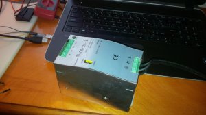
This is a 15VDC, 8A power supply I sampled a few months ago and finally just tested. Works good.

120-220VAC input and DIN Rail mounted.

IMG_20150512_185245.jpg
 
the power supply in the previous post works fine with the board to power and recharge batteries

tested the FX_LED today, 5 pins are not switching high/low but three might need different software enabled, and one was missed in testing

this board was shorted when an alligator clip went through electrical tape last week so its also possible the gates on the LED buffer were damaged or the Assembly drawing is mislabeled. the effected pads are showing either Hi or Low so its not a short (fabrication issue)

the 5V power supply is coming up OK when the PWR_ENBL1 pin is set high. its also showing the correct 5V

up next for today is to find the two ADC inputs from the battery charger. these showing high show a good battery and charging. low shows a bad battery and no charging

these will control indications in the UX

the SPI FLASH driver is missing one file for serialization, found it, we're going to include it

there are 5 untouched boards to test if software doesn't fix the gate issue on the LED Buffer. the pins are also multi-use so it could be the PWM file that's needed or they are defaulting to something else

but the good news is we're moving forward again
 
cleared up one of the pins for the FX_LED, so we're just down to a few on this board that are a question mark - if we cannot clear them, will test a different board that wasn't shorted

the software and such all work while recharging a battery so we're fully cleared to run and recharge

still working on adding new drivers and functions to the software for more tests - hoping we can clear up this flash driver so we can do the motor control next
 
some updates on progress. we're getting some direct help from Micron on the flash, we've tried all of the drivers and it still only works (with wrong information) using the generic driver

most of the UX is not done, its just adding the back end and navigation, user settings

will be working all weekend on the software, if we can clear up the flash issue, we can get a demo done inside a loco very quickly

http://www.layout-ioe.com/blogs/updates
 
Ilya got a driver working for the flash, it has bugs but this was the very first attempt with this file today after many failed attempts yesterday

I also got confirmation that there are no fabrication faults on FX_LED so I got a new board wired up tonight to finish the tests on it

If we can clear up the bugs on the flash, we're going to be ready for a locomotive demo very soon

Web-site's down tonight, should be up this weekend

SPI_GOOD.PNG
 
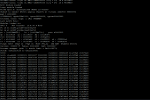
I am assuming from your wording that you know what's wrong with your kernel crash. Normally "ops" kernel messages are the results of a NULL pointer dereference or an incorrect pointer value. You are mentioning that you are having flash problems but Micron is working with you, so that is good.

I hope you can get this cleared up. Remember to not loose sight of the forest for its trees. You mentioned you are using busybox, so remember that a lot of tools (that people like me would like to have) are not included, so you need to put them back in. Again, I would love for you to leave an ssh daemon running on the box so we can get on it and add functionality (or give ourselves a funcussion doing it).

Thanks.

Ilya got a driver working for the flash, it has bugs but this was the very first attempt with this file today after many failed attempts yesterday

I also got confirmation that there are no fabrication faults on FX_LED so I got a new board wired up tonight to finish the tests on it

If we can clear up the bugs on the flash, we're going to be ready for a locomotive demo very soon

Web-site's down tonight, should be up this weekend


I am assuming from your wording that you know what's wrong with your kernel crash. Normally "ops" kernel messages are the results of a NULL pointer dereference or an incorrect pointer value. You are mentioning that you are having flash problems but Micron is working with you, so that is good.

I hope you can get this cleared up. Remember to not loose sight of the forest for its trees. You mentioned you are using busybox, so remember that a lot of tools (that people like me would like to have) are not included, so you need to put them back in. Again, I would love for you to leave an ssh daemon running on the box so we can get on it and add functionality (or give ourselves a funcussion doing it).

Thanks.

We cleared up the crashing issue, just waiting on some responses to finish the flash driver and BusyBox is back in now as well.

There will be some end user functionality, I just haven't got to that point yet to figure out what and how we can implement it. My main focus right now is wrapping tested of the hardware so I know whether I know everything is going to work.

There is a lot of potential to open up things so I am going to keep that in mind for you all.
 
Status
Not open for further replies.


Affiliate Disclosure: We may receive a commision from some of the links and ads shown on this website (Learn More Here)

Back
Top