ModelRailroadForums.com is a free Model Railroad Discussion Forum and photo gallery. We cover all scales and sizes of model railroads. Online since 2002, it's one of the oldest and largest model railroad forums on the web. Whether you're a master model railroader or just getting started, you'll find something of interest here.
we have three drivers in progress right now, one is for the WiFi, one does the eCompass/motion, and the other is setting up for flashing the memory so we can begin in locomotive testing
the last driver after this is motor control, we should have the majority of the work done this coming weekend
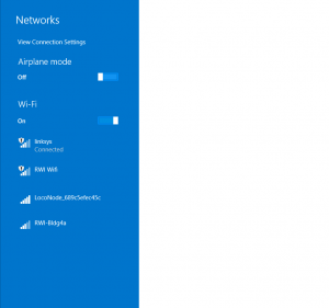
You can see the LocoNode on the WiFi networks seen by my Notebook. We got a driver working for the WiFi, now we just have to compress it more.
The driver for the motion worked as well but its configured for I2C, we need SPI so we have to rework it, though the driver is mounting during the booting.
We are now at a 100% complete for the surface components, and verifying the layout/fabrication/assembly.
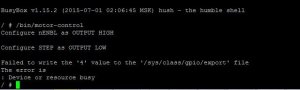
I got this last night, its only the second attempt at the motor driver and mostly works. It will be a few more days until its bug free and set up for locomotive type motor control.
Here was the program:
BusyBox v1.15.2 (2015-07-01 02:06:45 MSK) hush - the humble shell
/ # /bin/motor-control
Disable motor A: configure nENBL as OUTPUT HIGH
Disable motor B: configure STEP as OUTPUT HIGH
Set forward direction for motor A: configure DIR as OUTPUT LOW
Set forward direction for motor B: configure M0 as OUTPUT LOW
Put motor driver chip to sleep mode: configure nSLEEP as OUTPUT LOW
Configure nFAULT as INPUT
Configure M1 as OUTPUT LOW
Configure CONFIG as OUTPUT LOW
Put motor driver chip to !sleep mode
Enable motor A
Disable motor A
Set reverse direction for motor A
Enable motor A
Disable motor A
Enable motor B
Disable motor B
Set reverse direction for motor B
Enable motor B
Disable motor B
End of the testing sequence, exiting
/ #
I got this file two days ago, just able to run it now.
There are some bugs, the program is supposed to cycle up from 10% to 100% output on the motors but some fixes are needed.
It does run with the OMI SD70 though, and in this video you can see how the change between a track power source and the Li-PO is smooth, there are now power interruptions as you would get on dirty track.
Should get a new file tomorrow to show the full range of motor control.
We got an expanded program working for the battery fuel gauge - now we just have to adjust and compensate the values
We also got a BitBanging app working so we can flash our SPINAND. The first test worked. We need a recompiled BSP now, should be ready to fully test it tomorrow night.
This means we can get the board loaded with our firmware, boot, and also set up the WiFi. We have a WiFi driver ready but it will not flash because the manufacturer supplied tool is not working right. Three months and still no instructions from them.
This is great news, it means by this time next week, the OMI SD70 will be working with our board under WiFi.
the SPINAND has been successfully written, formatted, and can read data on it
there is a compatibility issue though with the internal boot ROM in that it cannot read our SPINAND
not sure if we can fix with a UBOOT file or not, its 50/50
I have 100% of the design tested and verified, we'll slide over to LN0001S-V1.5 for shipments and continue software with the development board and V1.4
I had Juan over last night, he's now set up with a working sample he can work with so there are three full time engineers plus myself on the software now
The issue for us is we need to be able to reboot to bring up the WiFi antenna because its defaulted off using USB booting needed to flash the SDRAM but we're still able to test and run programs to get everything finished up
I have the files ready and parts for 16 boards at the factory already for V1.5
today's agenda is more improvements in the motor control, I said on the video at one point, this test was done at 25 Mz but it actually was 50 Mz, we're going to do tests at 15 Mz and 25 Mz next. then we'll fix up the speed curves.
we're also going to add more content to the display then add the head light and back up light
we have a program that will get WiFi loaded onto the node after USB booting, so today we can also test the WiFi
We've progressed a lot further than the last video posts. The motor control program is in place and now we're tying in the LED's.
LN0001S-V1.5 has been ordered. This clears up the hardware snag on the audio and the software issue of incompatible boot ROM with our flash.
The new boards will be here in a few weeks.
The major change for these are the addition of a TV out pin which will enable the use of a monitor and Windows Embedded down the road for programming, debugging. We're also putting on a 4 GB eMMC flash.
Software will continue on the current boards for now. We should have the non-sound Loco programming done by time the V1.5 get here. Its possible to get the sound version done too but I assume it will have a bit more time trying to tie the sound engine in with the motor control based on the start/stops we've had with the LED's. Right now the PWM based outputs of the LED system are split and working, the GPIO based lights are almost there but driver overlap has blocked some of our initial efforts. I should be able to have that fixed tonight though.