ModelRailroadForums.com is a free Model Railroad Discussion Forum and photo gallery. We cover all scales and sizes of model railroads. Online since 2002, it's one of the oldest and largest model railroad forums on the web. Whether you're a master model railroader or just getting started, you'll find something of interest here.
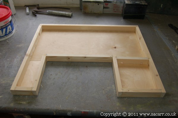
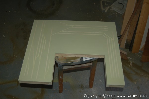
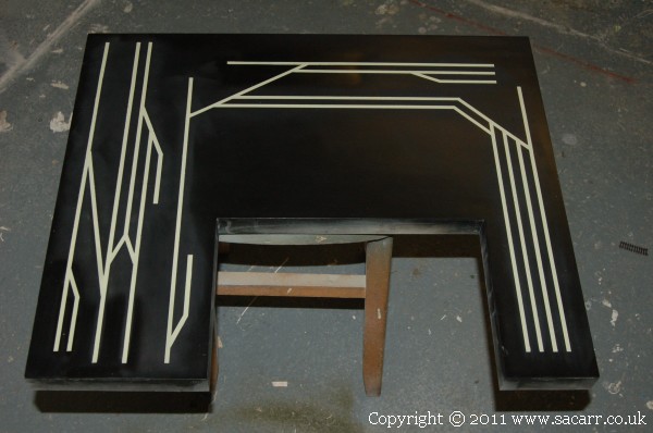
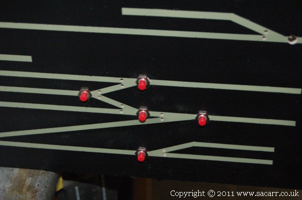
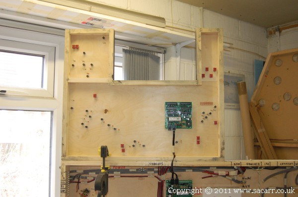
The rest of today was spent making the control panel for the Quayside, Yard and Countryside Station sections. A basic timber frame with 1/16 plywood gives a nice thin surface to mount switches and LED's into. The 'U' shaped panel allows a little more leaning room to reach over the panel to access the yard.
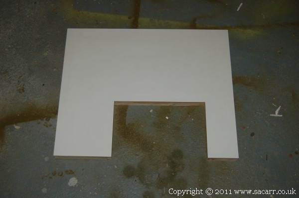
The upper surface was skinned in styrene to give a nice surface for the panel.
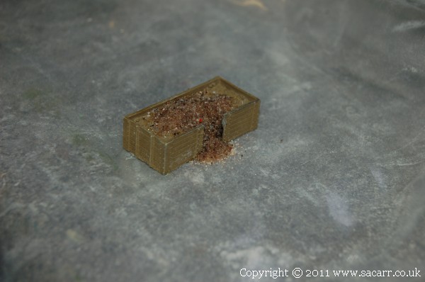
Here's the modified coal wagon. The coal around the door was ground out with a mini drill, and replaced with sand glued in with thin cyano. The coal that was spilling out was also made from sand, but this was done with the wagon sitting on a tough plastic bag. Once the cyano set the sand in place, the bag was peeled away leaving a nice flat surface on the bottom.
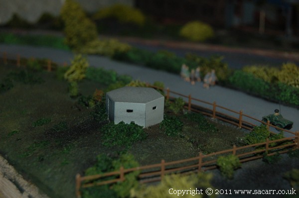
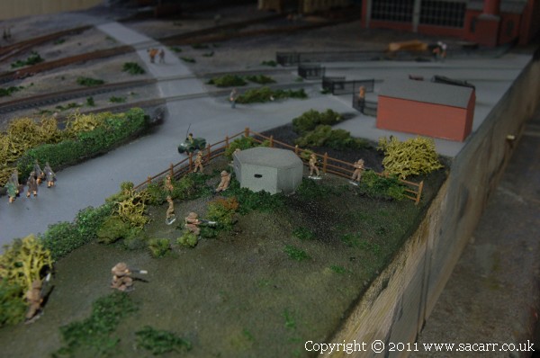
The pill box was painted, speckled, windows painted and glued down to a sand mound used to level the top of the small rise in the field. More greenery was added around the base. Just need to add some home guard troops around it.
Several soldiers had their bases trimmed down and were glued on around the pillbox. I left a bit more of the base on these figures. They are white metal and a bit heavier than the plastic figures, so I wnated a bit more gluing area than just their feet. They seem to be engaged in a combat exercise.
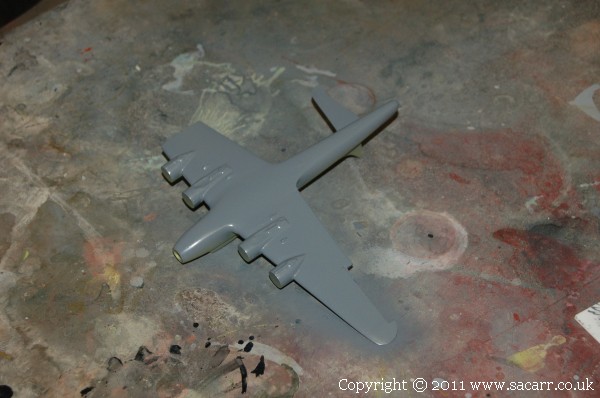
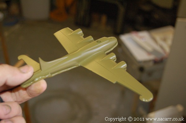
The B-17 castings were also cleaned up. This was done between paint drying and castings curing. Front and rear fuselage sections, left and right wings, tailplanes were cleaned up, glued and sanded. Because the plane is to be a 'Hangar Queen', a stripped down, war weary airframe, used for salvaging usable parts, a number of parts would be cut away.
One tailplane was left off, one outer wing panel was cut off, engines were left off, top turret is missing and a hole drilled where it mounted. The bombardier/navigators compartment was also drilled out. It is seen here in primer and with the underside grey painted.
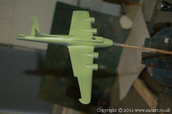
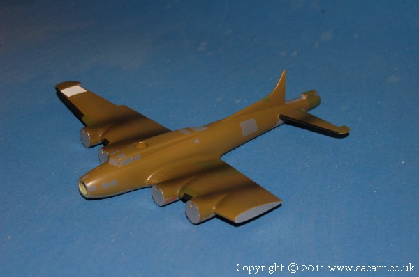
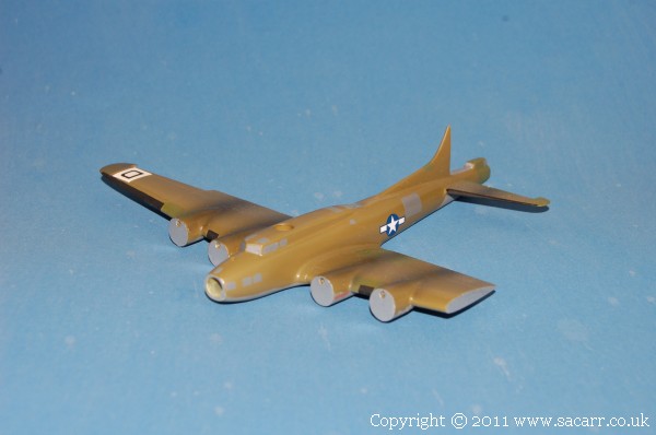
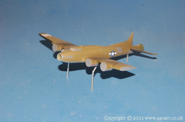
July - The 'Hangar Queen' B-17 was masked around the underside grey with sausages of 'Blu-tack'. This gives a slightly softer line than masking tape between the two colours. The olive drab looks a bit odd under the light of the flash, but is a reasonable representation of faded OD for this 'War Weary' salvaged plane.
It can be seen that it has already been gutted of many useful parts to keep the other aircraft in the Bomb Group flying. This was common practice during the war when the ground crews realised it was going to take more spares than their paperwork would allow.
The following day saw some more slightly random shades of green added, windows painted on, the beginnings of the markings and oil staining across the nacelles and wings.
While I was waiting for some figures to dry ( another 200! ), I made a start of the Lancaster for the airfield. It will be a little while before I need all the aircraft, but it makes a nice change of pace and keeps the build interesting.
This Lancaster will be set in a little diorama of its own on the airfield. The airbase is American, but the Lancaster has made an emergency landing after returning from a raid with battle damage. Towards the end of the landing run, one of the undercarriage legs collapsed, dropping the aircraft onto one wing tip and skidding it off the edge of the runway. The emergency crews will be on the scene, but fortunately no fire!
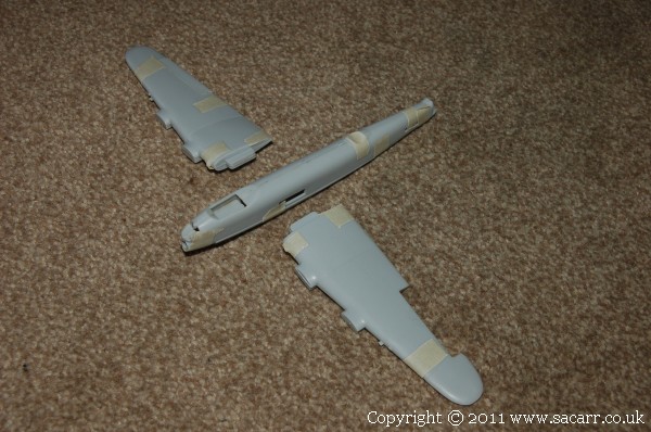
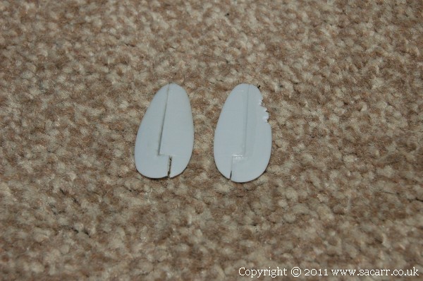
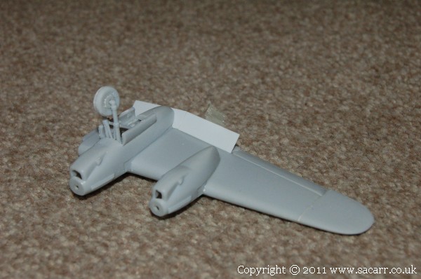
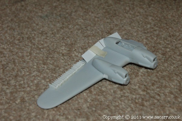
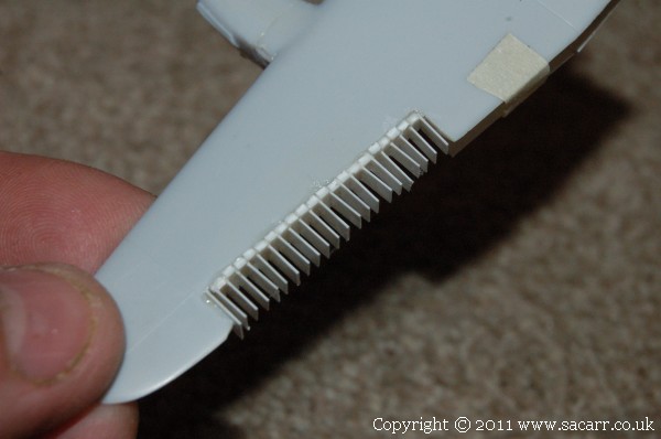
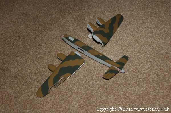
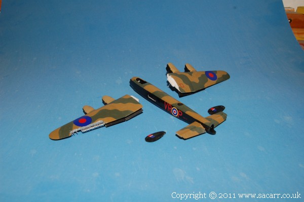
The first step was to join the fuselage and wings, then leave them to dry before the seams can be sanded and filled. One aileron, the one on the port wing was cut out and will be replaced with a skeleton structure where the fabric has burned away. The other was cut free and repositioned slightly.
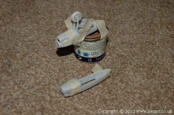
The two inner engine nacelles were glued together, and the one good undercarriage leg fitted. The kit wheel was thickened up with a layer of styrene as the kit wheels were much too thin to be an accurate representation of the Lanc's big balloon tyres.
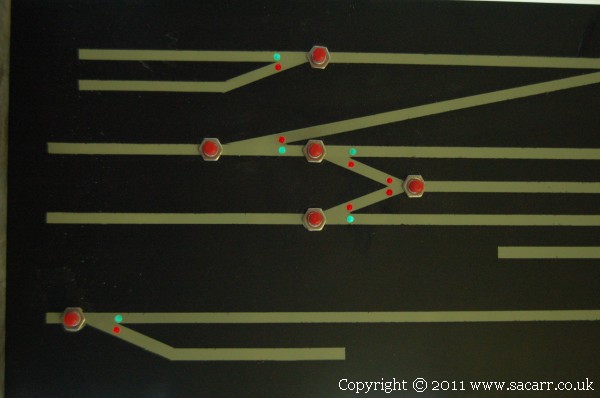
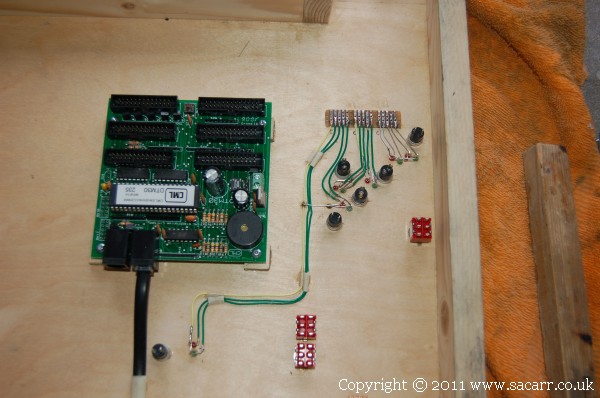
More work on the control panel. This will control the Quayside, Yard and Countryside Station sections. The point operation will be via a CML Electronics DTM30 control unit. I links into Loconet and behaves like a throttle, but uses push buttons to send the coded message to the DAC20 decoder circuit. It also has the benefit that routes can be programmed into the circuit to change all the points along that route.
Push button switches operate the points while the red and green LED's indicate point direction. The instructions for the panel circuit suggested the same colour LED's but I thought Green for straight, and Red for curved setting of the points would allow the operator to see what route is set at a greater distance from the panel.
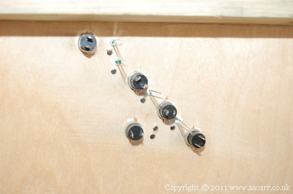
Push button switches fitted, and LED holes drilled.
Clamped to the yard section, the panel has had the DTM30 control panel circuit added. The switches for track isolation are also fitted, and everything is now ready for wiring. It is possible that this panel will be hinged on the bottom of this section to allow all the wiring between the two to be connected, and the panel stored folded under the section for storage and transport. This will allow all the wiring to be permanently connected.
Wiring! DCC is supposed to make things simple, but there's more wires ended up in the control panel than on the whole of my last layout!
There's loads of wires to sort out for all the LED's indicating point direction. They will be connected by a ribbon cable to the DTM30 circuit board, but peeling pairs of wires off this ribbon to all the LED's would end up very messy and look like an explosion in a spaghetti factory, especially since each set of four LED's share a common anode.
Instead, all the LED's have wires back to a strip of circuit board mounted in a convenient position. The ribbon cables should now be able to be wired up fairly neatly between the DTM30 module and the strips of PCB, and it should be easier to trace faults.
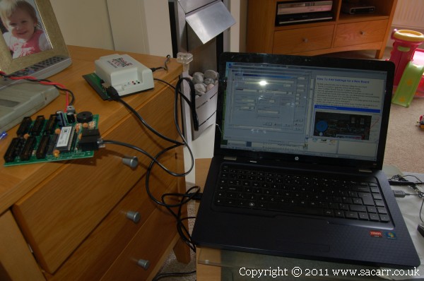
Figuring out the PR3 programmer, DTM30 control panel, laptop and software, and getting them all talking to each other took some doing. CML Electronics have a downloadable program to use with all their devices, but I found the program wouldn't run on my new laptop running Windows 7, but it would run on XP. I got there in the end, and was able to start entering test values into the DTM30.
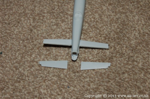
After a hard day working in the garden, I managed a couple of hours on the Lancaster. The elevators were cut from the tailplane so that they can be repositioned, and the tailplane was glued into the fuselage. The tips of the elevators are actually part of the tailplane, and will be cut off and glued to the tail once that has set in the fuselage.
Both rudders were cut from the fins and repositioned, and one rudder chewed up a bit.
The beginnings of a new aileron was made in skeleton form from thin styrene. When finished, this will be partly burned away from an incendiary shell. The over sized ribs will be left to fully set and then trimmed to the section of the wing.
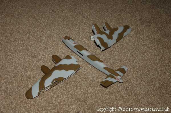
Because the fuselage side is black above the wing position, it made sense to paint the wings separate from the fuselage to save masking.
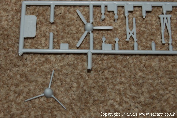
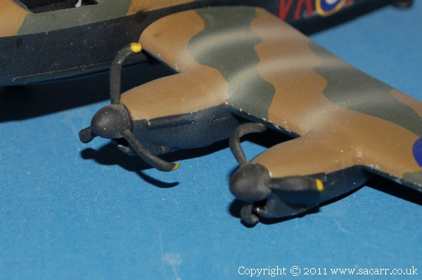
While the dark earth was drying, I modified one of the propellers to show the blades in the feathered position. 'Feathering' a prop turns the blades in line with the airflow, so that after an engine failure, the propeller blades don't spin around causing drag. The feathered prop is removed from the sprue while an original is seen still attached as a comparison.
Green came next, but it was a bit thin straight out of the tin, so will need a second coat.
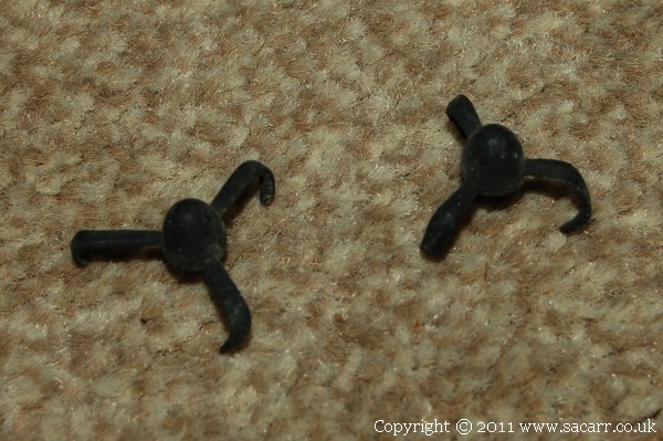
Two props from an old model were found for possible use on the side of the aircraft where the undercarriage collapsed. I need to check how close the engines are to the ground once the model is assembled, and if they are bent too much, I'll modify the kit props.
The B-17 saw a bit of action too. The stars were added to the fuselage side. The Bomb Group code letter has also been painted onto the wing.
The Lancaster was masked for the black underside and that was brush painted. Once dry, the aircraft was painted in 'Future', better known in the UK as Johnson's Floor Wax. It dries with a very glossy finish because it self levels. This gives a very smooth finish for the decals to go on, reducing the chance of any silvering under the clear parts of the decal.
'Future' is also great for dipping clear plastic parts in. It makes clear kit parts much clearer. The Lanc needs a little exhaust staining, then both aircraft need a matt coat to seal everything in.
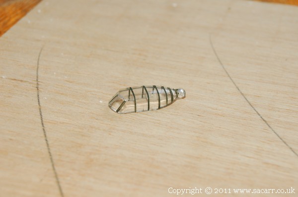
The Lancaster canopy has lots of frames on it. They are moulded into the glazing, though difficult to see. The easiest way to paint them was to mask them in stages, all the vertical frames first, then once dry, all the horizontal ones. This removes the need to cut lots of small rectangles of masking to cover each glazed panel. Instead, long strips of masking can be used which is easier to apply. The horizontal frames are yet to be applied.
The B-17 also had some wire legs added, bent vertically down to glue into the baseboard. The wheels will be glued to the sides of the wires after painting. The B-17 also had a matt coat sprayed on.
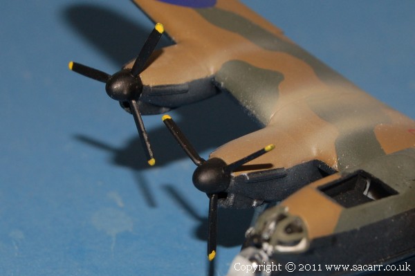
The wings had exhaust staining added freehand with the airbrush, and all parts were sprayed with a matt coat. The model was then assembled and props added. Two bent props on the side where the undercarriage collapsed, and the good prop and feathered prop on the starboard side.
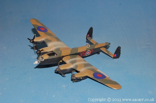
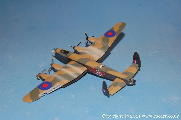
Here's the Lanc assembled and with the turrets and bomb aimers glazing fitted. The white glue can still be seen as white in the turrets as it hadn't dried when the pictures were taken. It will dry clear. There's still a piece of blutack on the bomb aimers glazing as this was used to hold the glazing while it was glued in place. It can't be removed until the glue has fully dried. The bottom of the port fin was also ground away where it has scraped along the runway during the landing.