ModelRailroadForums.com is a free
Model Railroad Discussion Forum and
photo gallery. We cover all scales and sizes of model railroads. Online since 2002, it's one of the oldest and largest model railroad forums on the web. Whether you're a master model railroader or just getting started, you'll find something of interest here.
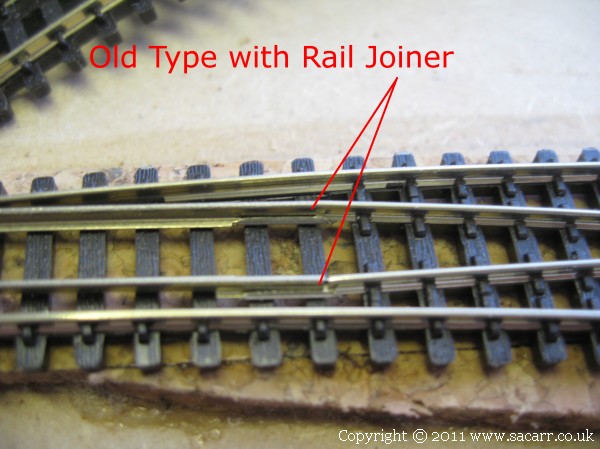
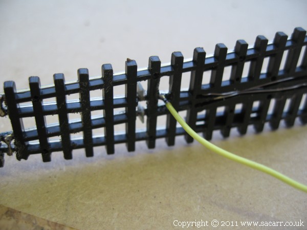
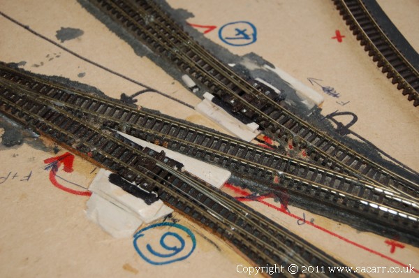
Since my last layout, the design of the Peco medium radius points has changed. I'm guessing this is to try and improve electrical conductivity through the switch rails to the frog. The original design had a rail joiner on the end of the switch rail which formed the pivot for the rail. Power to the frog relied on the switch rail making good contact with the stock rail, and this rail joiner having a good contact with the rail leading to the frog. As you can see from the photo, there isn't much contact area.
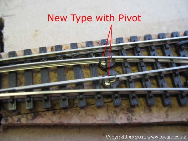
The new type have what looks like a rotary pivot, possibly with micro sliding contacts which would be self cleaning, and as a result give better electrical continuity.
The curved Peco points which I have just bought, still have the old style rail joiner, and so are less reliable. I've had problems in the past with either dirt between the switch rail and stock rail or in the rail joiner. Either situation prevents power getting to the frog, resulting in the locos stopping on the point. I saw a modification on the internet to improve conductivity which is what is shown in the following photos.
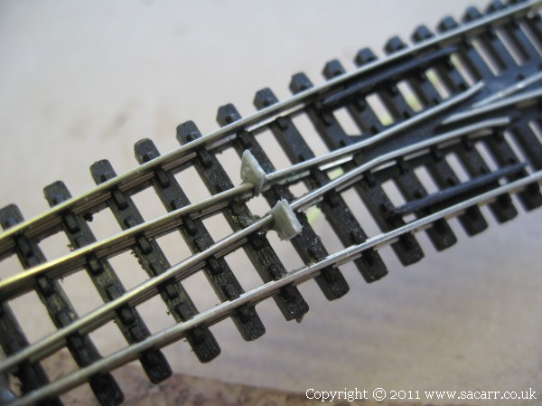
The middle rails near to the frog are cut through to isolate the frog from the switch rails. Small pieces of styrene were cyanoed into the slot, and trimmed flush with the rails once dry.
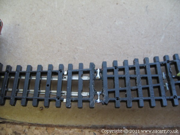
On the underside of the point, the plastic was cut away and a linking wire soldered between the stock rails and the fixed rail that the switch rail pivots from. This provides a solid electrical bond to these rails, and also means that the switch rails now have two sources of power; from the blade touching the stock rail and from the pivot end via the linking wire.
Power to the frog now comes from another wire soldered to the bottom of the frog. The polarity of this wire is changed by a Peco PL13 switch attached on the bottom of the point motor, changing the polarity as the blades change.
After a conversation with the customer, we decided to modify the new design points too, due to the improved reliability with the modification. With a layout as big as this, keeping the track clean is going to be a huge task anyway, so this modification should reduce dirt affecting point operation.
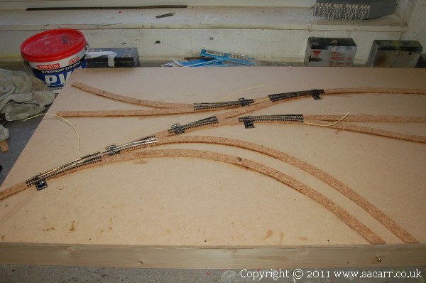
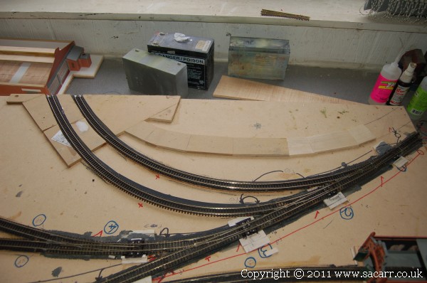
The cork road bed was glued on yesterday, so was fully dry today. Once the other points were modified, the holes were cut in the baseboard for the point motors.
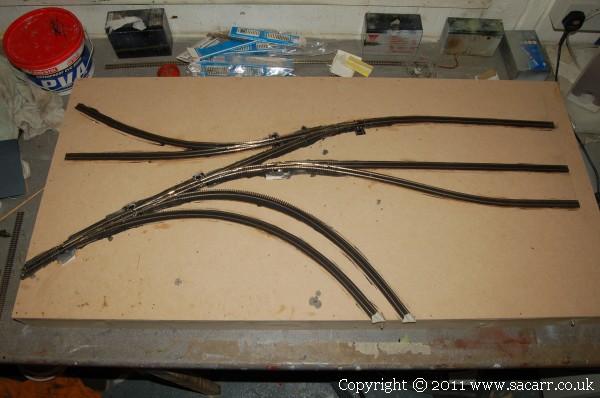
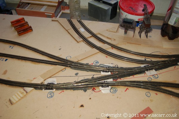
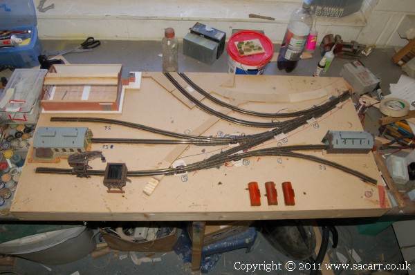
All the track is laid on section two! The only bits which aren't finished are the ends that will connect to the quayside. For that I need some more brass screws to solder the rails to, and I need to join both boards to align the rails. The track radii look quite sharp leading to the quay, but the minimum radius is still 12 inches and a loco test proved satisfactory.
After the Easter break and Royal Wedding Bank Holiday, all of which was taken up by servincing and a brake overhaul on my Dodge Weapons Carrier, then a weekend away at a military show, I finally got back to the layout on May 10th.
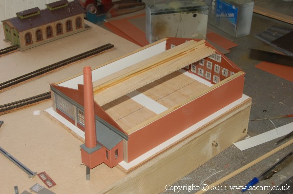
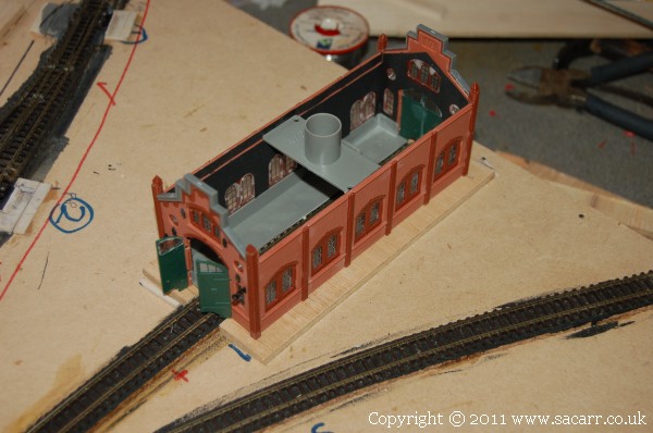
I've been modifying some old buildings into new ones for the next section. The first to be changed is a two bay round house being converted into a large factory building. No pictures at present, but all four walls are standing on their base, and supports are in for the roof.
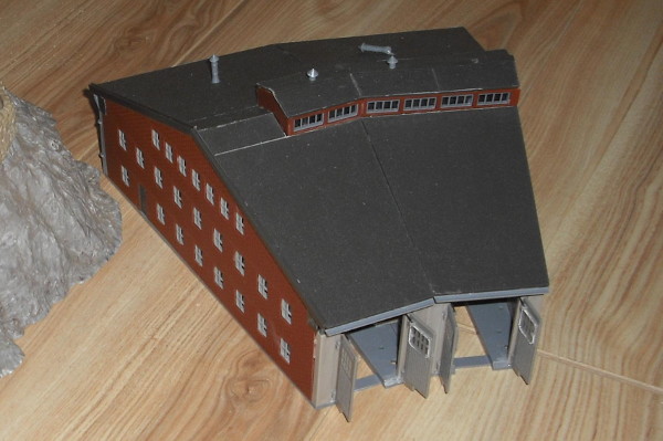
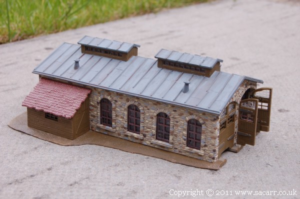
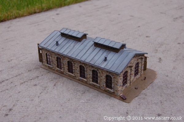
Here's the roundhouse kit before modification. The kit was built ok, but was falling apart because it was glued with tube glue rather than a liquid solvent. The tube glue had gone rubbery, or was that way to start with, and the building just didn't have a solid feel to it.
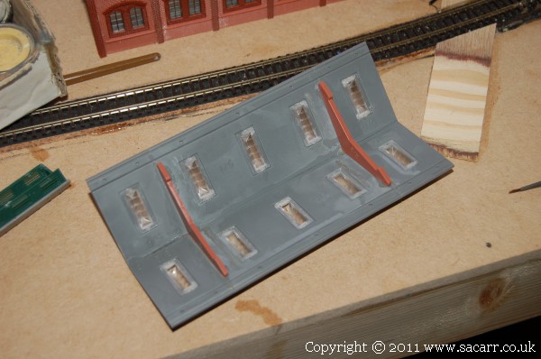
and how it looked after the modifications had been started.
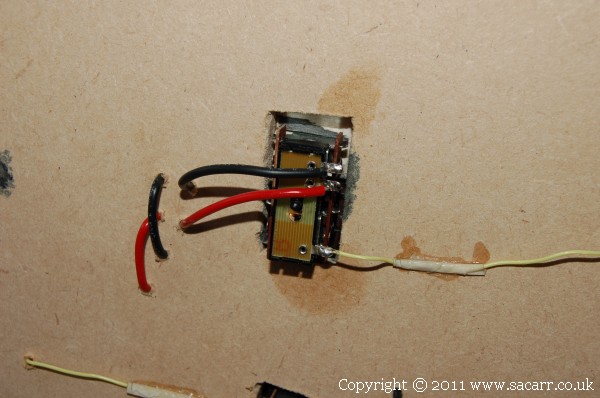
That was left to dry, and I moved back to the electronics. The first step was to fit the PL-13 switches to the bottom of the point motors. A couple of small drops of cyano held them in place, being careful not to get glue on the sliding mechanism. The power feeds from the track to the switch came next, along with the switch to the frog connection.
The track power feeds were fitted at the same time as the frog wiring, linking all the main sections of track. Two tails of wire were left at each end of the board to connect these power feeds to the ring main.
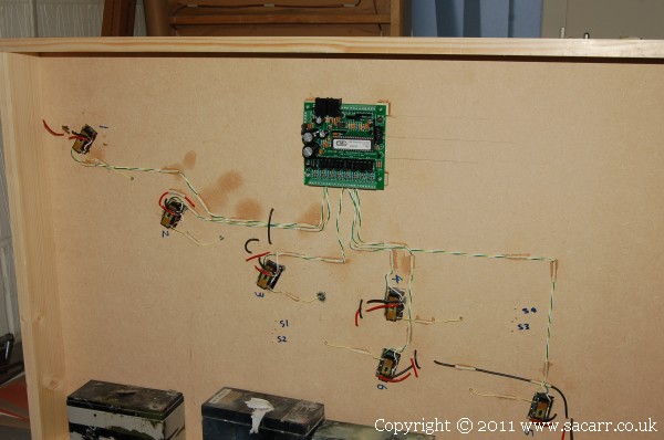
A CML Electronics DAC20 point decoder was screwed onto four ply mounting pads with small brass spacers to allow plenty of airflow around it. The wires from the point solenoids were connected next, and routed back to the DAC20, but not connected at this time. The CML decoder is compatable with the Digitrax Loconet operating system, but can operate eight points or switch sixteen on/off devices. The quayside section used a Digitrax DS64 which only operates four points.
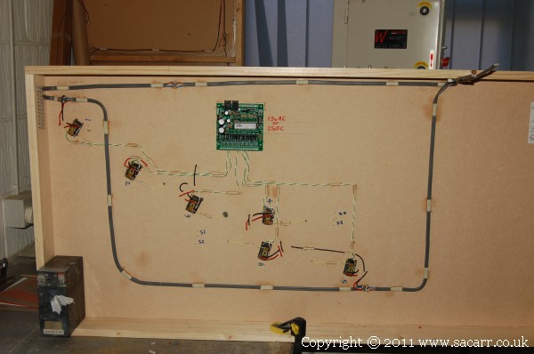
The last job of the day was to attach the ring main wiring for the track power supply. This is mains power cable, a nice large section copper wire to reduce resistance.
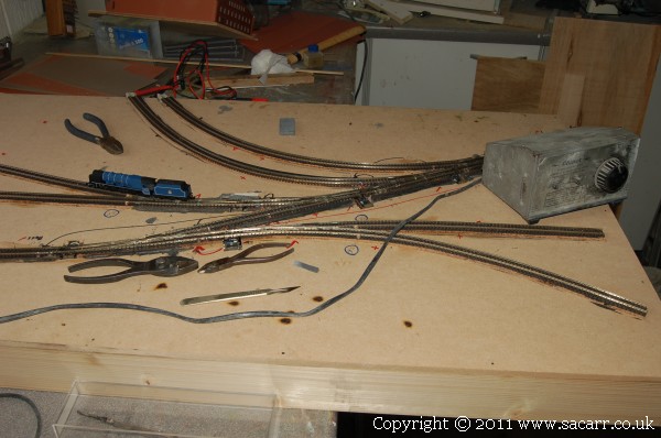
Power feeds were temporarily attached to the track, and one of my locos test run across the points, everywhere except the four isolated sidings which will have their power supplied through the control panel.
It doesn't look a huge amount of progress for a days work, but it's another step along the way!
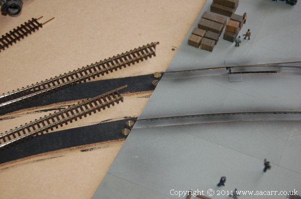
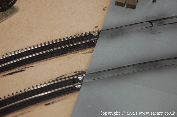
Mid May - With both baseboards bolted together, brass screws were inserted at the boards edge where the rails meet the first section. The rails were trimmed, and tinned with solder, as were the screw heads.
The rails were then pulled into place, being careful to maintain the curve of the first section. The rail was then heated with the soldering iron until the solder flowed between the rail and screw head. Using a screw also meant that it could be screwed in or out prior to soldering to get the rail height a perfect match to the first section.
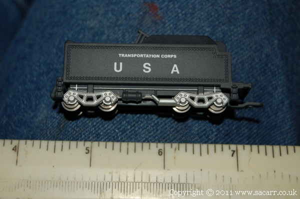
This K4 static loco is another 'import', freshly off loaded from a ship. The original markings were removed and it was re-lettered with 'USA' from normal Letraset rub down lettering. Since the dawn of the computer age, rub down lettering is getting harder to find, and I could find any really small lettering for the words 'Transportation Corps' above the USA.
A little while ago, I contacted a friend who has recently bought the equipment to make his own rub down decals. Nigel did some tests and was able to make the following 'Transportation Corps' lettering which is only 3/4 of an inch long, and a little over 1/32 of an inch tall. This opens up all sorts of possibilities for other lettering and logos around the layout.
Further wiring on the loconet connections is another job out of the way. An email to the DCC point and control panel supplier clarified some issues over power supplies as everything uses different voltages. The best way around this is to have a mains supply around the layout, and individual transformers to drop the voltage to each unit. Apparently a common supply can cause feedback issues through the loconet connection. With so many points etc., on the layout, I didn't want to power them from the track supply.
1/4 inch MDF was glued on where the road will be, matching the height to the first section. This will decend slowly to baseboard height, lowering the road in relation to the track height.
The holes around the point motors were also filled in with balsa wood to allow ballasting without it falling out through the baseboard.
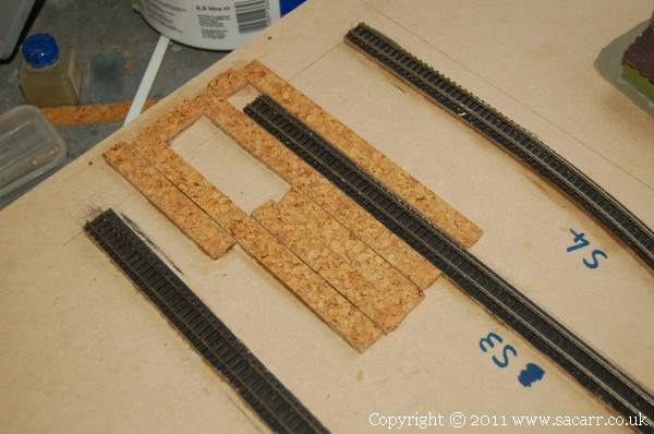
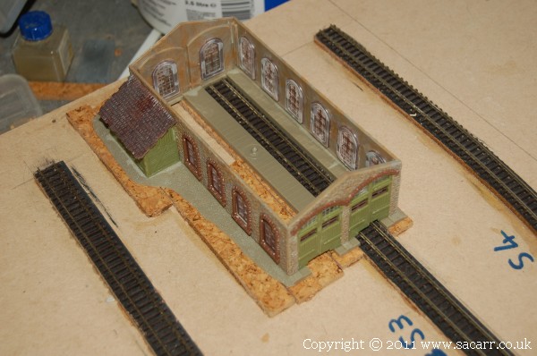
A cork base was added where one of the buildings was going to bring the building up to the correct height in relation to the track.
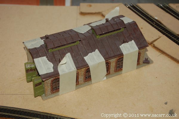
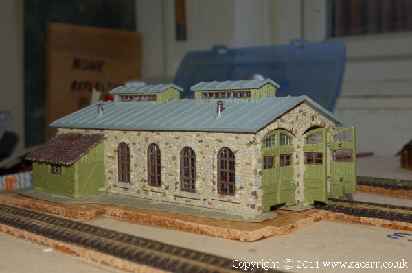
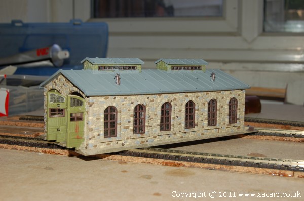
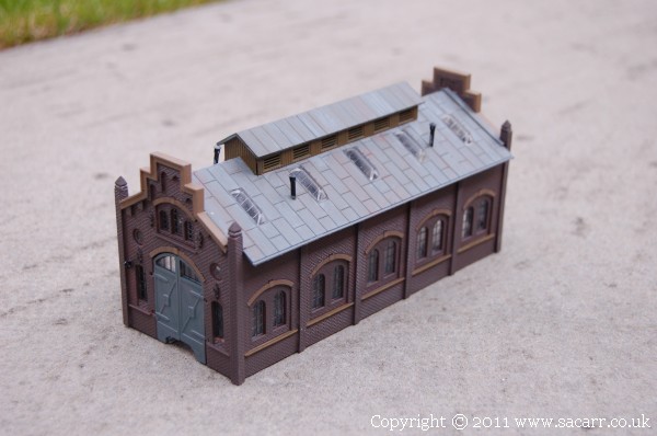
This is the building after the first part of the refurbishment. The shed on the side had all the seams re-glued, and it was re-attached to the main building. The main building wasn't dismantled, but just had liquid glue run into all the joints. The roof was already off the building when it arrived.
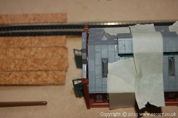
The other loco shed was treated the same way with the seams all being re-glued. It appeared that it was built with tube cement rather than liquid solvent cement.
The roof was actually made from eight pieces, six roof pieces and two braces, plus skylights. The skylights were left in place, but all the other parts were separated, cleaned up and re-glued.
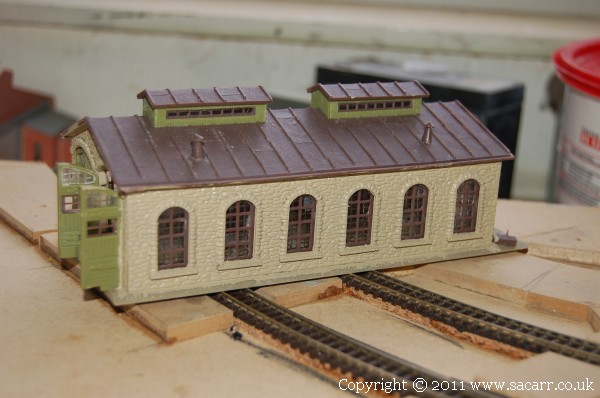
The first building had its roof glued on followed by the stonework being given a coat of paint. The whole building would be repainted during its restoration.
The roof was painted a base of grey, followed by some detail painting of the stonework in a few different shades. Once again, the camera flash makes it look a bit brighter, and the contrast more harsh, than it actually is. The small shed, doors, roof vents and chimneys still need painting, the stonework needs a wash, and the roof needs some weathering.
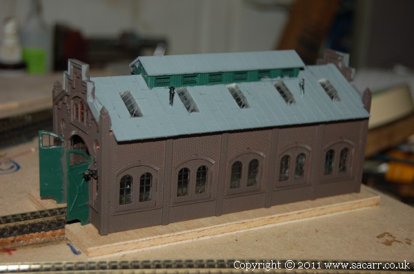
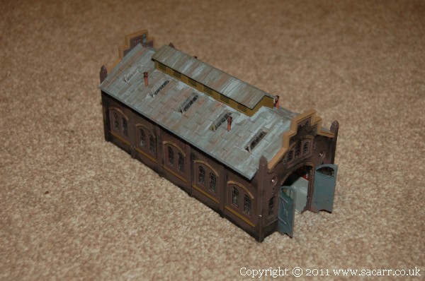
Back to the second loco shed. Once the roof repairs were set, I went to fit it, only to find it about 1/16 inch short each end! Not sure why, but I hadn't noticed it before as this roof was also loose when the model was sent here. A few small strips of styrene filled the gaps. After gluing, the walls were painted in brown brick.
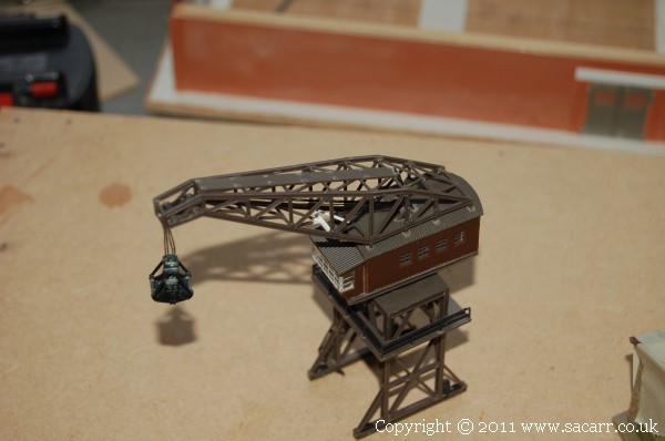
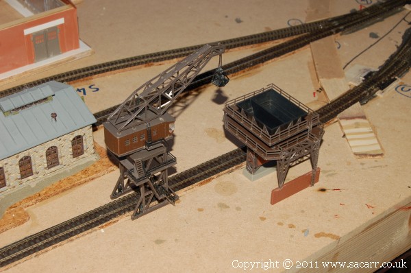
The crane and coal loader were further second hand buildings, both of which were battered about in the box on their way to me. They are both shown after being repaired, but before painting.
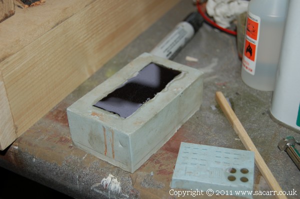
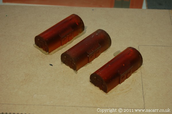
Three Nissen huts were cast as additional buildings, and I'm also planning a Romney hut, also typical for quaysides. The Nissen huts came from the mould I made for my 'Kingman' layout.
The Romney hut more often found on military bases was a 17ft 6in radius hut, built in multiples of 8ft long sections, typically 96ft long. On the model this will be around 3 inches diameter and about 7.75 inches long.
The first Nissen hut in the mould.
and the three castings ready to be cleaned up and painted.
A second road foundation was added across the board.
and an overall view of this section so far.
Further painting on the crane, coal loader and weathering a loco shed pushed these models on to completion.
Before weathering
and after. Again the artificial light makes the contrasts much harder than they really are. I really need a photo studio as well as a workshop!

Affiliate Disclosure: We may receive a commision from some of the links and ads shown on this website
(Learn More Here)