I just got some flex track and am fighting to fit not a tight curve but one rail, the loose, always sticks out. Is that normal ? Do I have to cut it off to fit the other connecting rail ? This is my first time I'm "working", more like fighting with Atlas flex track. Can somebody tell me what to do and how ? I even got a bit desperate and think of getting some Atlas 24" radius curves, the largest available of Code 100, but definitely need a larger radius. Any tips, please. Thanks.

You are using an out of date browser. It may not display this or other websites correctly.
You should upgrade or use an alternative browser.
You should upgrade or use an alternative browser.
Use of flex track, please help !
- Thread starter csxfan
- Start date
ModelRailroadForums.com is a free Model Railroad Discussion Forum and photo gallery. We cover all scales and sizes of model railroads. Online since 2002, it's one of the oldest and largest model railroad forums on the web. Whether you're a master model railroader or just getting started, you'll find something of interest here.
Yes, it's normal for the rail to stick out. It's basic geometry. The inner rail is a smaller radius than the outside rail. A given length applied to a smaller radius will create a greater arc length than the larger radius. This is why cars have differentials.
The proper method for joining flextrack on a curve is to let the last 2" or so of the track 'hang' straight. Trim off any extra length from the loose rail and solder on a new stick of track. Then continue laying the track through the curve as normal.


")
Mike


slide the joiner in then solder the joint in place.
Doing so will end up with something that looks like this where zero ties were destroyed or replaced in making the connection. This is the only place that I solder track - flex track on a curve that is.....

Using the solder on bench method that was used at our club before I explained above you can end up with things like this.
Edit - Oops sorry, I should have read the rest of the thread before I posted. I guess I could have just said - "what Selector said".
It is the standard in the HO scale, Atlas. In my case, Code 83. There is track with better detail, and it costs somewhat more. Micro Engineering has nice track, and Proto 87 has very nicely detailed track and details you can add, but you have to have the right kind of rolling stock for that precision track, including locomotives. They have to have the correct wheels and gauge.
Thanks Crandell, some manufacturer's sites don't give a really good close up of the ties etc. The Atlas looks more than adequate.
Yes the holes are quite noticeable, specially in Crandell's pics. Only solution would be to fill them and brush them to match the grain and then paint. A bit of unwanted messing about.


Affiliate Disclosure: We may receive a commision from some of the links and ads shown on this website (Learn More Here)
TheGloriousTachikoma
Member
I just got some flex track and am fighting to fit not a tight curve but one rail, the loose, always sticks out. Is that normal ? Do I have to cut it off to fit the other connecting rail ? This is my first time I'm "working", more like fighting with Atlas flex track. Can somebody tell me what to do and how ? I even got a bit desperate and think of getting some Atlas 24" radius curves, the largest available of Code 100, but definitely need a larger radius. Any tips, please. Thanks.
Yes, it's normal for the rail to stick out. It's basic geometry. The inner rail is a smaller radius than the outside rail. A given length applied to a smaller radius will create a greater arc length than the larger radius. This is why cars have differentials.
The proper method for joining flextrack on a curve is to let the last 2" or so of the track 'hang' straight. Trim off any extra length from the loose rail and solder on a new stick of track. Then continue laying the track through the curve as normal.
HOexplorer
Well-Known Member
Solid and joined together ties on the outside of the curve helps too. Jim
railfan
junk collector
Here's another question: If you need a longer length of flex track.....to go around a curve......longer than a single section......should you solder two sections of flex together while holding them straight?....with the special flex mating tool that is normally used?....then bend them around the curve?
I'm also new to the flex track thing.
Mike
I'm also new to the flex track thing.
Mike
railfan
junk collector
Ok....I see my question is answered right here. Very good!The proper method for joining flextrack on a curve is to let the last 2" or so of the track 'hang' straight. Trim off any extra length from the loose rail and solder on a new stick of track. Then continue laying the track through the curve as normal.
Mike
Selector
Well-Known Member
Many experienced modellers recognize that the last two inches of a length of flex will not bend. Try it and see for yourself....I'll wait. 
See? So, if you need two lengths joined to make a nice sweeping curve, how to you make the curve a nice consistent radius? Or, if you finish a curve at a tangent, and the join just happens to be where the two full lengths, one curved and one tangent, meet, how will you make those last two inches fashion a nice transition curve, or what is called an easement?
The answer is to solder the two together on a flat surface, but with both of them straight. Then bend them in place. However, it isn't quite so simple. The inner sliding rail will stick out, as you have found. What many of us do is to slide the long rail into the set of spike details of the adjoining piece, and displace the next piece's rail by a commensurate amount. Solder there. In fact, what I do is use a jeweler's saw to cut a joiner into four small pieces. It takes the patience of Job and the vocabulary of a sailor to get that tiny bit of joiner into place between two ties that are closer than if they had been on a tangent, but it can be done. See the image below. This is in the middle of a two deck helix with 33" and 36" curves on a double main.

The point is that you can slide at least one rail into the next length of flex for about five or six ties worth and reduce that kink immensely.
Or, you can actually bend both rails at the end. It takes some practice, a stout constitution, and some wasted bits of flex track, but you can actually impart a permanent shallow bend into the very tips of a length of flex and save yourself all sorts of grief and struggle with jeweler's saws, tiny bits of joiners, and knowing you'll have to explain yourself to St. Peter ere long.
See? So, if you need two lengths joined to make a nice sweeping curve, how to you make the curve a nice consistent radius? Or, if you finish a curve at a tangent, and the join just happens to be where the two full lengths, one curved and one tangent, meet, how will you make those last two inches fashion a nice transition curve, or what is called an easement?
The answer is to solder the two together on a flat surface, but with both of them straight. Then bend them in place. However, it isn't quite so simple. The inner sliding rail will stick out, as you have found. What many of us do is to slide the long rail into the set of spike details of the adjoining piece, and displace the next piece's rail by a commensurate amount. Solder there. In fact, what I do is use a jeweler's saw to cut a joiner into four small pieces. It takes the patience of Job and the vocabulary of a sailor to get that tiny bit of joiner into place between two ties that are closer than if they had been on a tangent, but it can be done. See the image below. This is in the middle of a two deck helix with 33" and 36" curves on a double main.
The point is that you can slide at least one rail into the next length of flex for about five or six ties worth and reduce that kink immensely.
Or, you can actually bend both rails at the end. It takes some practice, a stout constitution, and some wasted bits of flex track, but you can actually impart a permanent shallow bend into the very tips of a length of flex and save yourself all sorts of grief and struggle with jeweler's saws, tiny bits of joiners, and knowing you'll have to explain yourself to St. Peter ere long.
Last edited by a moderator:
^^^Top answer, delivered succinctly
The full rail helps to keep the kink out of the joint in the other side and should be continued past the transition into the next straight length.
Iron Horseman
Well-Known Member
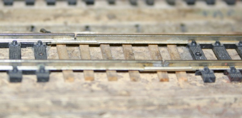
No, Because as the start of this thread shows the rails need to slide because the outside of the corner is bigger/longer than the inside. Set the first section down leaving the inside rail long. Slide the rail on the 2nd piece of track down out of the way leaving some blank ties. Slide the extra length of the first section into the ties of the 2nd section. This will offset the joint and keep the track in gauge by not destroying 5-10 ties. Use a hobby knife to cup out the ties where the rail joiner needs to go. The cup needs only to be the thickness of the rail joiner.Here's another question: If you need a longer length of flex track.....to go around a curve......longer than a single section......should you solder two sections of flex together while holding them straight?....with the special flex mating tool that is normally used?....then bend them around the curve?
slide the joiner in then solder the joint in place.
Doing so will end up with something that looks like this where zero ties were destroyed or replaced in making the connection. This is the only place that I solder track - flex track on a curve that is.....
Using the solder on bench method that was used at our club before I explained above you can end up with things like this.
Edit - Oops sorry, I should have read the rest of the thread before I posted. I guess I could have just said - "what Selector said".
Last edited by a moderator:
What brand of track is that, that both you (Iron Horseman ) and Selector are using? The spike plate and wood grain detail looks very good.
Selector
Well-Known Member
What brand of track is that, that both you (Iron Horseman ) and Selector are using? The spike plate and wood grain detail looks very good.
It is the standard in the HO scale, Atlas. In my case, Code 83. There is track with better detail, and it costs somewhat more. Micro Engineering has nice track, and Proto 87 has very nicely detailed track and details you can add, but you have to have the right kind of rolling stock for that precision track, including locomotives. They have to have the correct wheels and gauge.
It is the standard in the HO scale, Atlas. In my case, Code 83. There is track with better detail, and it costs somewhat more. Micro Engineering has nice track, and Proto 87 has very nicely detailed track and details you can add, but you have to have the right kind of rolling stock for that precision track, including locomotives. They have to have the correct wheels and gauge.
Thanks Crandell, some manufacturer's sites don't give a really good close up of the ties etc. The Atlas looks more than adequate.
Iron Horseman
Well-Known Member
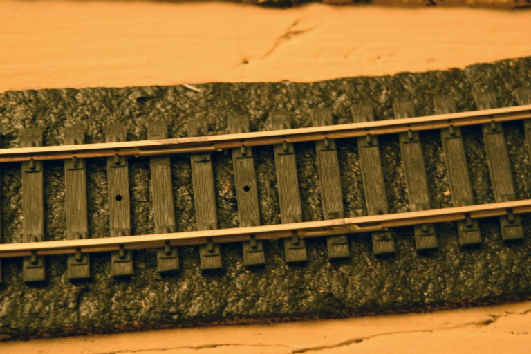
My photos are of standard Atlas code 100 track. The only issue I have with it is the gaping circle holes for nails that I don't use.What brand of track is that, that both you (Iron Horseman ) and Selector are using? The spike plate and wood grain detail looks very good.
Last edited by a moderator:
The photos are of standard Atlas code 100 track. The only issue I have with it is the gaping circle holes for nails that I don't use.
Yes the holes are quite noticeable, specially in Crandell's pics. Only solution would be to fill them and brush them to match the grain and then paint. A bit of unwanted messing about.
Don't believe it, them's real trains, can tell by the smoke. 
")


Burlington Bob
Well-Known Member
Just really good Lionel O gauge smoke units!!
Affiliate Disclosure: We may receive a commision from some of the links and ads shown on this website (Learn More Here)