Turnouts mounted above the base level. What to do with the motor?

ModelRailroadForums.com is a free Model Railroad Discussion Forum and photo gallery. We cover all scales and sizes of model railroads. Online since 2002, it's one of the oldest and largest model railroad forums on the web. Whether you're a master model railroader or just getting started, you'll find something of interest here.


videobruce

Tower Operator
Turnouts mounted above the base table level. What to do with the motor?

I see many just 'stack' pieces of rigid foamboard on top of one another to achieve the desired height for a 2nd, raised level as opposed to using 'T' supports (old school cookie cutter method). That's fine if there are no turnouts on this elevated section, but what do you do if there are?

Run a 2" to 6" rod up from the plywood base to reach the elevated turnout?? :confused:
 
Last edited by a moderator:
I would probably install a plywood subroadbed below where the turnout was so it would provide a solid mounting point for the tortise or I would just use a double throw double pole slide switch for the turnout contol and mount it on the ground next to the turnout. If I didn't want to bother with control signals, I would just use Caboose Industries turnout throws and mount them on the foam next to the turnout.


Have you thought about using Peco switches with Peco switch machines? They mount directly under the switch. Just cut a small hole out of your foam/subroadbed, to drop the switch machines down in there.

And the nice thing is, they are hidden.
 
It isn't that small of a hole. That is the problem. Hidden, sort of. Accessible, not if attached directly, especially if foam is used along with plywood.

Yes, I plan on using Peco turnouts, but not their machines for the above reason unless something changes.
Jury's still out.
 
Last edited by a moderator:
Well I have 24 of them on my layout.

Accessible? Why? It's not like they are failing and need replacing. They are very reliable. I never had any issues with any of them, for the 2 years that I've had them.

And you can add small peices of cork roadbed to cover the holes, thats what I do.

Can you spot in this photo were they are located? I have 1.5" of foam on top of plywood for my subroadbed.

P1000795.jpg
 
Last edited by a moderator:
But, that is HO scale, I have N.
And yes to your question. But if you do have a problem, then you have two.

I'm just looking down the road. Just like those overpriced built-in appliances that you can't get at. Poor reliability and hard to service. All just to be 'artsy-fartsy'. :rolleyes:
 
Last edited by a moderator:
On my N-scale layout, I use a system of music wire moving inside brass tubing to actuate turnouts through up to 5" of plywood and foam.

underside_servo_strap1a.jpg

turnout_linkage1.jpg


Although I use servos to move the wire, Tortoises or other turnout motors of your choice can use the same system.

- Jeff
 
I thought the whole point of Model Railroad layout scenery was to be "artsy fartsy".
That was referring to those appliances I described. :rolleyes:

jdetray; I have seen your pic of that mount setup many times. Precisely bending that wire would be a concern for me. Do you make some type a jig to do this? Since it is bent on both ends, which end is done last? The other question is, how do you secures the vertical portion of the wire so that you can bend the rest of it without destroying it?
How much are the additional electronics for position indication other than wiring up a relay?
 
Last edited by a moderator:


When installing one of these turnout actuators, I make only one measurement. Everything else is easily done by eye. With practice, you can install one in 10-15 minutes. The actuators are installed after the turnouts are in place on your layout. No jigs are required. Use 1/16" brass tubing and 0.032" music wire (also known as piano wire).

Steps are as follows.

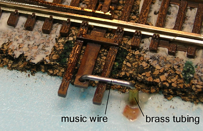
1. Select a location for the brass tubing, as shown in my photo above. I use a location that is 3/8" from the turnout throwbar. This is the only step where I measure anything, but even here extreme precision is not necessary. A little more or less than 3/8" is fine.

2. Drill a hole for the brass tubing. If you are installing through several inches of plywood and foam, you'll need an extra long 1/16" drill bit. I found mine at a big home center (Lowe's). But you can also purchase "aircraft" or "long boy" drill bits online.

3. Insert a long piece of brass tubing into the hole from the top of the layout. At this point, you have not cut the tubing to length, so you may be using a piece of tubing that is 2 or 3 feet long. Push until about 1" of tubing protrudes from the underside of the layout. On the top of the layout, mark the tubing where it emerges above layout. Now pull the marked tubing out of the layout and use a razor saw to cut it to length approximately 1/8" above your mark. De-burr the opening of the tubing so the music wire can slide in freely. I used a dull Xacto blade for de-burring.

4. Re-insert the cut piece of brass tubing until only about 1/8" extends above the top of the layout. Friction is probably enough to hold the tubing in place, but I use a dot of glue to be sure.

5. Cut a piece of music wire that is several inches longer than will be needed for the particular location. You'll trim it later. Music wire is cheap so be generous. Hint: Do not attempt to cut music wire with the little wire cutter you use for cutting hookup wire; you will ruin your wire cutter. Use the cutter built into needlenose pliers, or better yet, a heavy diagonal cutter or a pair of linesman's pliers. Music wire is tough stuff.

6. Make right angle bend approximately 3/4" (no need for precision here) from one end and drop the wire into the tubing from the top on the layout (the bend keeps it from falling through).

7. With the wire inserted in the tubing, lay the bent portion of the music wire across the throwbar and note the location of the hole in the throwbar. Use two needlenose pliers to grip the wire and make a small downward bend so that the end of the wire can drop into the hole in the throwbar. If the downward bend is too long, trim off the excess. This is all done by eye without measuring anything.

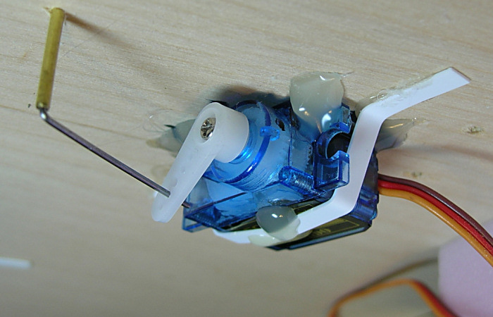
8. On the underside of the layout, you'll have at least a couple of inches of music wire extending out of the tubing. Eventually, you will bend this at a right angle just where it emerges from the tubing then trim it to a convenient length. However, you don't want to bend it or trim it until you determine the location of the turnout motor, be it a Tortoise, a servo, or some other type of motor. I happen to use servos. The music wire can be bent in any convenient direction so you have a lot of freedom in where you mount the turnout motor.

For electronics, I use the Tam Valley Depot system with servos. The costs work out to be about the same as using Tortoises. But the cost of the Tam Valley system includes everything: both pushbutton control and DCC control, a pushbutton switch and LED indicators for your control panel, and relays for switching frog polarity. If you don't want frog switching, you can save about $3 per turnout. By the way, the Tam Valley system can drive Tortoises, too, with an optional add-on board.

If you have any other questions, I will try to answer them.

- Jeff
 
First off, thanks for posting all of that. That should be a 'sticky'.

Questions;
1. Since I will have 65 turnouts (5 manual industrial spurs and 9 for the hump), can I 'mass produce' some of those steps? At least the top two bends and length of the wire?
2. I don't want DCC control of the turnouts, but do want position indication (except for those 14 mentioned above). How does that impact price or selection of whatever associated electronics needed? Could I just use separate relays like I did with my old Atlas motors for position?
 
Last edited by a moderator:
1. For all turnouts that sit atop the same thickness of plywood/foam, you can of course determine the length of tubing and music wire you will need and then mass produce those pieces. You will want to perform steps 1 and 2 for the first one, then measure the length of tubing and music wire required. Now you can cut all the brass and music wire needed for all turnouts that sit on the same thickness of plywood/foam.

2. There are circuit diagrams for turnout position indicators all over the web; do a Google search.

As far as how you move the control wire, that's totally up to you. You can use a Tortoise, a servo, a pushrod linkage that you move by hand, a homemade motor drive -- whatever method you like.

I happen to be familiar with the Tam Valley Depot product line, so their's is the only solution I can intelligently discuss.

They have a non-DCC product, the Octopus board, for driving servos for turnout control. One $32 board controls 8 turnouts ($4.00 per turnout). A controller (for your control panel) with a pushbutton and two LED indicators is $2.00 in kit form. The Tam Valley site also has circuit diagrams if you prefer to homebrew your own controllers/indicators. Servos can be purchased for about $3.00 each if you shop around.

So basic non-DCC turnout control using the Tam Valley Octopus boards will cost $4 + $2 + $3 = $9 per turnout, plus whatever it costs to buy the brass tubing and music wire and to mount the servos (I use hot glue.). If you want frog polarity switching and/or trackside signaling, you can add your own microswitch or purchase an add-on DPDT relay from Tam Valley.

To be clear, I have no vested interest in promoting Tam Valley products. I am simply a satisfied user and don't have experience with any other turnout control products. For all I know there could be a vastly superior system out there about which I know nothing!

- Jeff
 
Without a doubt, it seems to be either Tam Valley or Tortoise for motors according to all the threads I have seen here or elsewhere.
 
While the Tam Valley Depot non-DCC "Octopus" boards work only with servos, their DCC-compatible "Quad" boards can drive either servos OR Tortoises.

Also worth mentioning is that the Quad boards can be used with or without DCC. If you don't have DCC, you can still use the Quad boards to operate turnouts with the pushbutton/LED controllers. If you later move to DCC, you can then control your turnouts with DCC commands as well.

So if you like the Tam Valley system and might one day want DCC control of your turnouts, go with the Quad boards now, and you'll be all set for DCC whenever you choose. This is exactly what I did with my layout. I installed the Quad boards and servos while I was operating my layout on DC. It was several months later that I purchased a DCC system.

- Jeff


Affiliate Disclosure: We may receive a commision from some of the links and ads shown on this website (Learn More Here)

Back
Top