Engauge18
New Member
Hello All,
New to the forum.
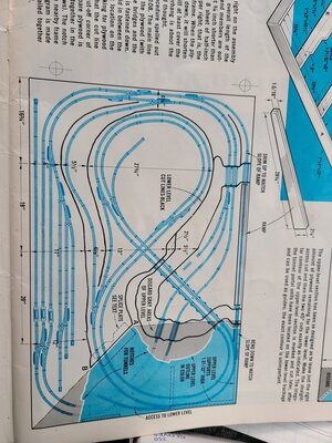
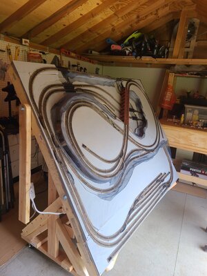
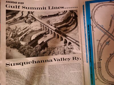
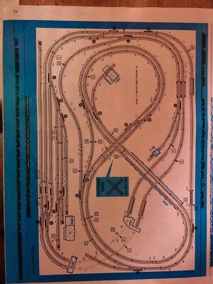
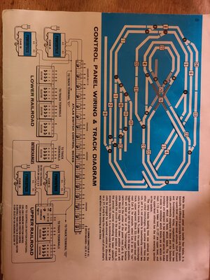
Have built up the 'famed' Gulf Summit & Susquehanna Lines' railroad from the Atlas Nine N Scale Railroads book (N-109). For those not familiar, this is an old book, first published in the 70s. It's all analog wiring and code 80 track. It's a cookie cutter bench work design that has two separate railroads each with double track. It can run 4 locos simultaneously and independently, all in 4'x6'.
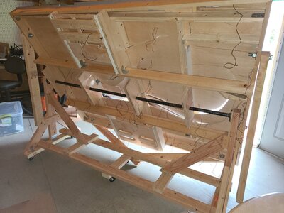
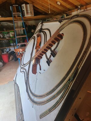
I built my version of this on a tilt table frame.
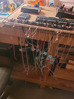
Question for the group: having trouble writing the second cab on the main line. The upper level has no issues with running 2 locos, it's the lower level that gives the issue.
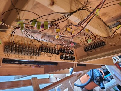
The wiring diagram calls for sending a lead from one DC terminal on each cab to the main line 'C1'. When i do this though, only the second cab can run a loco.
I tested each cab and loco separately and they with fine. It's something in how I'm connecting the two cabs.
Thank you for your help!
New to the forum.
Have built up the 'famed' Gulf Summit & Susquehanna Lines' railroad from the Atlas Nine N Scale Railroads book (N-109). For those not familiar, this is an old book, first published in the 70s. It's all analog wiring and code 80 track. It's a cookie cutter bench work design that has two separate railroads each with double track. It can run 4 locos simultaneously and independently, all in 4'x6'.
I built my version of this on a tilt table frame.
Question for the group: having trouble writing the second cab on the main line. The upper level has no issues with running 2 locos, it's the lower level that gives the issue.
The wiring diagram calls for sending a lead from one DC terminal on each cab to the main line 'C1'. When i do this though, only the second cab can run a loco.
I tested each cab and loco separately and they with fine. It's something in how I'm connecting the two cabs.
Thank you for your help!