
You are using an out of date browser. It may not display this or other websites correctly.
You should upgrade or use an alternative browser.
You should upgrade or use an alternative browser.
Track Main Bus?
- Thread starter wombat457
- Start date
ModelRailroadForums.com is a free Model Railroad Discussion Forum and photo gallery. We cover all scales and sizes of model railroads. Online since 2002, it's one of the oldest and largest model railroad forums on the web. Whether you're a master model railroader or just getting started, you'll find something of interest here.


Bend the clip so it makes a loop, the two ends fasten to the block, solder the wires to the loop and insulate.

Two Terminal blocks, (most are + and - but you can simply jump them), so lets say 15 set's of droppers, that's 30 wires, going to 2 or 4 Distribution Boards, neat and tidy ? it'll look like a flipping spiders web.
Simpler to run a buss wire in a loop underneath in line with the track above and connect the dropper wires to that as, and where, you need them.


Dave


Affiliate Disclosure: We may receive a commision from some of the links and ads shown on this website (Learn More Here)
Snowman
Well-Known Member
I don't see why not, and yes, it makes sense. Your big problem then is connecting the X end of the wires to the terminal block, which might allow for only a couple or three, at most, direct wrap wires...and even then it's all too easy for them to pop off under compression from the screw's head pushing against the block.
The right way to solve that would be to connect each X end to a terminal eyelet, but you can only stack so many of those in the confining arc between the blocks side protection extrusions, which are designed to prevent too many of them fouling with the others directly off to each side.
However, the right way to solve THAT is to connect a number of the terminal screws to the same...bus... ...laid right along the whole terminal block, and all in a line. Do that on both sides of the terminal block, + on one side, and to ground on the other, with one or more connections then to each screw.
Which I think what you are asking in the first place, right?DDD
Yes, that ^ should work.
There is one complication though, and I'm going by memory here: Don't terminate each individual bus on its own. IIRC you want to terminate them all together again at a single point at the farthest end of all of them, to maintain the same range of voltage for each one over the length of each individual bus.
Of course I could have that last bit all Bass-ackwards, and it's the other way round: Terminate each individually, but not together.
Meh! Now we need to hear from someone who actually knows what he's doing. I hate that................
The right way to solve that would be to connect each X end to a terminal eyelet, but you can only stack so many of those in the confining arc between the blocks side protection extrusions, which are designed to prevent too many of them fouling with the others directly off to each side.
However, the right way to solve THAT is to connect a number of the terminal screws to the same...bus...
...laid right along the whole terminal block, and all in a line. Do that on both sides of the terminal block, + on one side, and to ground on the other, with one or more connections then to each screw.Which I think what you are asking in the first place, right?
DDDYes, that ^ should work.
There is one complication though, and I'm going by memory here: Don't terminate each individual bus on its own. IIRC you want to terminate them all together again at a single point at the farthest end of all of them, to maintain the same range of voltage for each one over the length of each individual bus.
Of course I could have that last bit all Bass-ackwards, and it's the other way round: Terminate each individually, but not together.
Meh! Now we need to hear from someone who actually knows what he's doing. I hate that................
") Okay - that makes sense as much sense as any electrical does to me
Okay - that makes sense as much sense as any electrical does to me 
Snowman
Well-Known Member
You'd want TWO of these, one for all reds and another for all blacks.
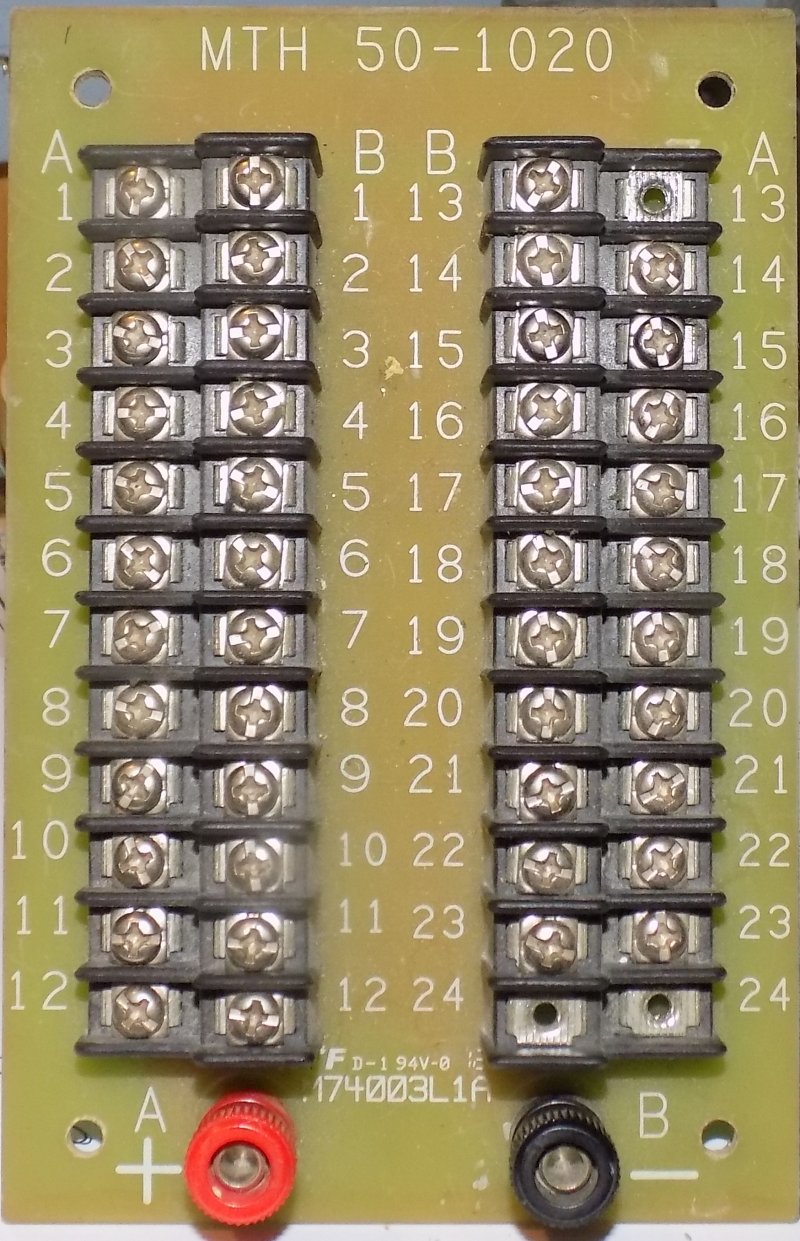
Those blocks let you configure pretty easily, making them all common on one side using the red connector, and to your (red or black) source to one power line along each side (not both sides, just the one) simply passing across. It's used for something like connecting a device with a short lead--a Tortoise, for example--to a much longer wire on the opposite terminal. Each circuit is isolated from the screws next to it on both sides even though common (in your case). If you want each completely isolated from its neighbor to each side instead, just leave the buss bar off entirely. Then the block is just a place to join the connecters (like a spade terminal) and keep them all in one convenient place.
To connect all on one side to a common source, you WOULD add that red multi-connector/aka the short "buss bar" to one side (there is a photo of that configuration that on the left, #6 from the left) The entire block would also be connected to your source by adding a wire (from that source) to just one end of the end screws or the other. You've sorta done that with your diagram, where you've drawn all the pins on one side as red, but on the other side as black, you haven't drawn anything actually connecting them to make then all red or all black--you've just colored them red and black as though they are...somehow joined. But those ^^^ blocks come with the common buss connecter that actually does it.
What you would really want instead is TWO terminal blocks, one black and one red, each screw joined by it's common buss bar on one side, and then connected to each track lead off the screw on the other side (each pair is pass-through connection, each across from one side to the other. The way you've drawn it here, the screw on one side does NOT connect to its opposite number--its all + one side, all - on the opposite side. But there is no reason to have common red and common black on opposite sides of the SAME terminal block. Just use two. They are cheap enough.
If you want to locate them near another physically, that's easily enough done, as long as you keep the red block electrically separate the black block.
You common connect each block along each side for the same source (say +) using the red joiner buss joiner. Each terminal is pre-spaced to the next one too. Pretty handy.
Photo #6 shows it--and then you just connect one end screw on the buss side to all the rest by using a separate line to your source. You've drawn that here to your power source.
Each connects to it's opposite screw (across the block), and then goes off individually to where you want it (to various joints along the red rail).
Last edited:
Smudge617
Well-Known Member
Yes, easiest way I know to do that would to use something like a paper clip.Can you run a set of wires from your controller track connections to a Terminal Block and then run X Amount of sets of wires for track power from that terminal block?
Does that make sense?
Bend the clip so it makes a loop, the two ends fasten to the block, solder the wires to the loop and insulate.
Hutch
Well-Known Member
The purpose of the block is to avoid soldering and keep things tidy. I think Snowman gave the best advice here. 2 blocks one for each leg or split one in half with the first 4 red and the second 4 black or however many connections you need.Yes, easiest way I know to do that would to use something like a paper clip.
Bend the clip so it makes a loop, the two ends fasten to the block, solder the wires to the loop and insulate.
Smudge617
Well-Known Member
Right, now I've caught up and Tony's explained his thinking, I'm going to respectfully disagree with just about everything above, including my previous post.The purpose of the block is to avoid soldering and keep things tidy. I think Snowman gave the best advice here. 2 blocks one for each leg or split one in half with the first 4 red and the second 4 black or however many connections you need.
Two Terminal blocks, (most are + and - but you can simply jump them), so lets say 15 set's of droppers, that's 30 wires, going to 2 or 4 Distribution Boards,
neat and tidy ? it'll look like a flipping spiders web.Simpler to run a buss wire in a loop underneath in line with the track above and connect the dropper wires to that as, and where, you need them.
Last edited:
Lynnb
Well-Known Member
Tony I have done this sort of the same but used a power shield 4 to divide into districts https://dccwiki.com/Power_Shield_X . But otherwise just running a supply to a block and then route out from there should be no issues as long as you‘re utilizing a power strip with a circuit breaker, keep in mind I’m no electrician. I actually have two busses , one with the PS 4 for the the rail buss and the other off an old power pack controller for my tortoise switches.
Hutch
Well-Known Member
This makes the most sense to me and is what I plan on doing. I have a feeling there's more to Tony's plan that I don't understand. More pictures Tony? Wait is this the Give Tony Grief thread?Simpler to run a buss wire in a loop underneath in line with the track above and connect the dropper wires to that as, and where, you need them.
logandsawman
Northern Pacific history enthusiast
Thats what I did. My train is DC not sure if that matters.Can you run a set of wires from your controller track connections to a Terminal Block and then run X Amount of sets of wires for track power from that terminal block?
Does that make sense?
Dave
Smudge617
Well-Known Member
No, but it seems like it, the rule is this KISSThis makes the most sense to me and is what I plan on doing. I have a feeling there's more to Tony's plan that I don't understand. More pictures Tony? Wait is this the Give Tony Grief thread?
Lynnb
Well-Known Member
This is the way my rail buss is set up over two room , the 12/2 wire is in such a location under the bench work so the drop feeds can route to them , each set of buss wires starting from a Pover Shield circuit breaker board which gets its feed from the Digitrax command station.Right, now I've caught up and Tony's explained his thinking, I'm going to respectfully disagree with just about everything above, including my previous post.
Two Terminal blocks, (most are + and - but you can simply jump them), so lets say 15 set's of droppers, that's 30 wires, going to 2 or 4 Distribution Boards,
Simpler to run a buss wire in a loop underneath in line with the track above and connect the dropper wires to that as, and where, you need them.
migalyto
Well-Known Member
Thats exactally how i plan on doing it.Can you run a set of wires from your controller track connections to a Terminal Block and then run X Amount of sets of wires for track power from that terminal block?
Does that make sense?
Smudge617
Well-Known Member
I agree, simple and neat, I don't have power district's simply because like Tony's present layout, it's not large enough, but why make simple stuff so complicated.This is the way my rail buss is set up over two room , the 12/2 wire is in such a location under the bench work so the drop feeds can route to them , each set of buss wires starting from a Pover Shield circuit breaker board which gets its feed from the Digitrax command station.
migalyto
Well-Known Member
It's just figuring out what terminal blocks are best. There are so many options.I agree, simple and neat, I don't have power district's simply because like Tony's present layout, it's not large enough, but why make simple stuff so complicated.
Smudge617
Well-Known Member
A Distribution Board has many uses, I use mine for lighting as each DB has it's own on/off switch, so I can have some lighting like buildings off, but streetlights on.It's just figuring out what terminal blocks are best. There are so many options.
wombat457
I'm the one
Grief - what have I caused ??
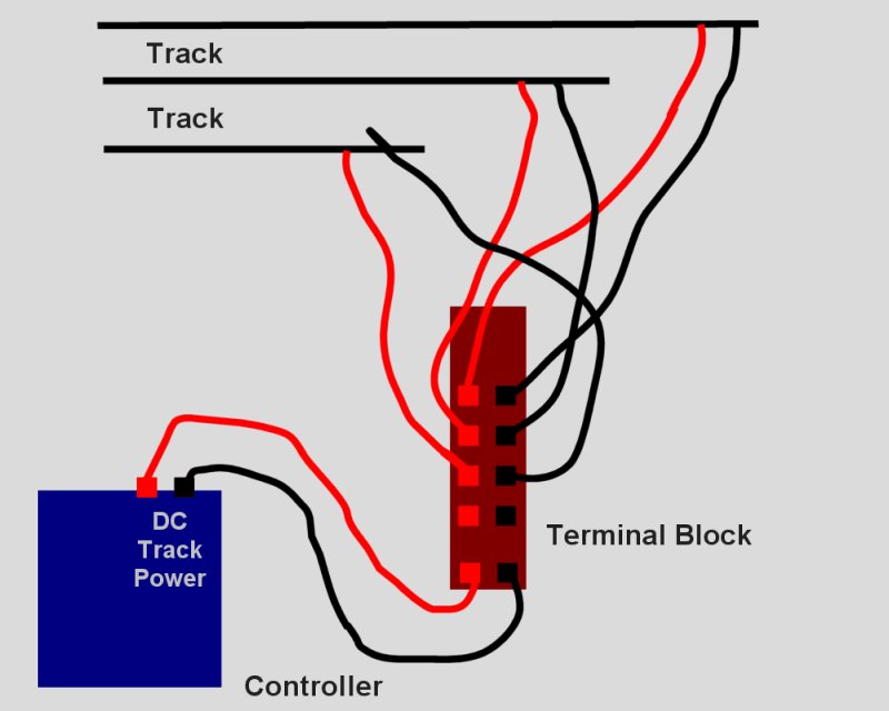
I probably didn't explain things too well and the diagram I used just made things worse I think. So hopefully this will explain everything:
Instead of having ONE Main Bus with a number of joins in it to create other bus wires (3 loops so 3 main buses if you like) I want to run each of the main buses from a terminal block that has segregated + and - terminals as I have drawn, and yes they exists, I have a number of them.
My way of thinking is this should be able to be done without any complicated explanations. Instead of running my track bus from the controller I'll be connecting the controller to a terminal block and running the Bus Wires from it instead. This has nothing to do with Drop Feeders, like the diagram probably suggests. If there is a reason that can't be done, okay then it can't be done for some reason and I'll just do it the old fashioned way.
Affiliate Disclosure: We may receive a commision from some of the links and ads shown on this website (Learn More Here)