Track feeds kato ho

ModelRailroadForums.com is a free Model Railroad Discussion Forum and photo gallery. We cover all scales and sizes of model railroads. Online since 2002, it's one of the oldest and largest model railroad forums on the web. Whether you're a master model railroader or just getting started, you'll find something of interest here.


Bristolman2012

Active Member
Have my layout ( kinda ) figured out . If wiring guru could help it would be appreciated . The passing siding has the insulated uni joiners on all 8 legs ( turnouts ) as I am adding switch motors to them . The siding is powered . The outside track on rt side will have 2 single truss bridges with maybe spacing between them . I’m using kato in curves and then using all code 83 track for bridges and track till next kato curves .
Mike
IMG_1036.jpg
 
DC or DCC might make a difference on feeders.
You may not need insulated joiners on all the siding rails.
 
Last edited:
A feeder set on each end in the center of each curve, a feeder set in the middle of each straight, and a feeder set in the middle of each siding would be more than enough.


If you mean drop feeder wires from the buss to the rails yes, I use bell wire for the short distance.
 
Looking at the layout above, I'd just use the Kato electrical unijoiners (which is what I used, drilling holes through the table to keep the wires invisible).

I also used the Kato "extension cables" and "3 into 1" adapters when needed.

Thus everything comes down to one set of leads to attach to my dcc controller.
 
I started making my own track feeders because not only size of the holes to feed them thru layout table plus the cost to power my layout ( 3 loops ) with those ? Already a little afraid to figure out what I’ve spent for track and all those other accessories .


Bristol wrote:
"Appreciate the thought , I just don’t like the size of holes u have to drill in the table to get the connector through"

You don't have to do that.

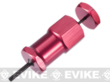
I got something called (I think) a small tamiya pin tool. With it, I pushed the pins out of the plastic shells. Now I could drill a smaller hole, run the wire through, and put the pins back into the plastic shell.

Works great. I would push the "bare" wires down to the holes, then run them through to get the UniJoiners where they needed to be.

I also did this (at the "UniJoiner end"):
1. I located the drilled hole about 2" away from the actual joint, to provide some "wiggle room".
2. I separated the blue and white wires for about 2" from the UniJoiner. Again, makes it easier if you have to break the joint apart.

Again, works fine.
 
B
Bristol wrote:
"Appreciate the thought , I just don’t like the size of holes u have to drill in the table to get the connector through"

You don't have to do that.

I got something called (I think) a small tamiya pin tool. With it, I pushed the pins out of the plastic shells. Now I could drill a smaller hole, run the wire through, and put the pins back into the plastic shell.

Works great. I would push the "bare" wires down to the holes, then run them through to get the UniJoiners where they needed to be.

I also did this (at the "UniJoiner end"):
1. I located the drilled hole about 2" away from the actual joint, to provide some "wiggle room".
2. I separated the blue and white wires for about 2" from the UniJoiner. Again, makes it easier if you have to break the joint apart.

Again, works fine.
believe or not i was just looking online for that , pretty pricey though . One guy took an ink pen apart and wiggled it around and pushed the pin out .
 
found old electronics tool , cant even remember where i got it . removed all of the white connector ends .i had added power switches to all of the manual turnouts so i can drill small hole . soldering skills suck but going to do dpdt momentary switches for tunouts . j albert do you have any crossover swiches in your layout ? my layout a triple loop so wont be able to do 2 inces away wiggle room . if i measured right i only have 3/4 of an inch between the kato tracks . thanks again for feedback ,i kept looking to resolve problem .
 
Here's the tool I use for popping the wires out of the plastic connectors:

By 2" wiggle room, I mean that I drill the hole for the Power UniJoiners about 2" from the actual location where the track joint is. I found that doing this gives more "room to maneuver" when working with the track. Works for me.


Affiliate Disclosure: We may receive a commision from some of the links and ads shown on this website (Learn More Here)

Back
Top