Thinking of Switching LED brands


I'm thinking of switching from the Bowerful brand LEDs https://www.amazon.com/dp/B07P6L7P6V/ref=twister_B07P8RTKCF?_encoding=UTF8&psc=1
51%2BB9X5qb5L._AC_SL1200_.jpg


to these https://www.amazon.com/10pcs-prewir...ired+0603+red+led&qid=1626046835&s=hi&sr=1-14
41SVlAoHfbL._AC_.jpg


Or perhaps https://www.amazon.com/uxcell-Prewi...ired+0603+red+led&qid=1626046791&s=hi&sr=1-12
61oSicUWpFL._AC_SL1100_.jpg


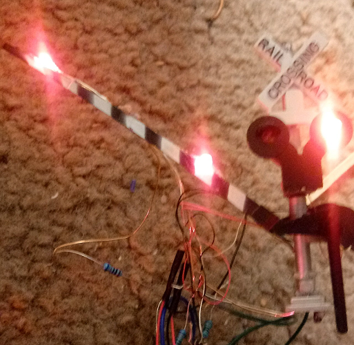
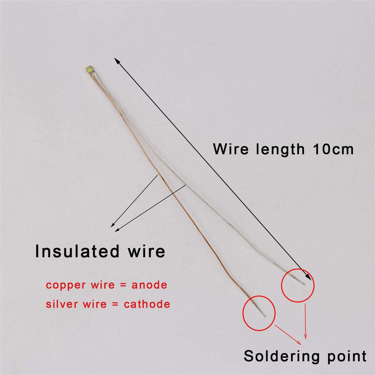
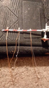
It's because the Bowerful-brand LEDs I've been using have not been working so well for me. I think one reason is the leads, though insulated, are metal and look more like bare wires, not rubber-covered wires like I hoped they'd be and like other wires I use, wires with easily peelable insulation. And when the metal leads touch each other though they are insulated, it causes my LEDs not to work the way I want them to, at least not completely and they malfunction. If my crossing gate arms are not positioned right and the arms are a bit short, the Bowerful LEDs will either not light up at all, light up dimly, or not light up right (for example, the light at the tip of the gate, which is supposed to stay on at all times, flashes.) My gate lights don't always work realistically or like they should. And I've been wrestling with my LEDs to make them work right. And many of them have burnt out and I've used my last one, and I had 25 of them! I've only lit five of my crossing gates including four of my NJI 1172 crossing gates. And I've had to switch out the LEDs, removing the out-of-service LEDs and putting in their place the good LEDs.

I don't think I'll be using the Bowerful-brand LEDs anymore and I recommend you don't either, at least not for HO crossing gates.

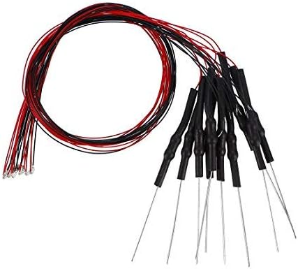
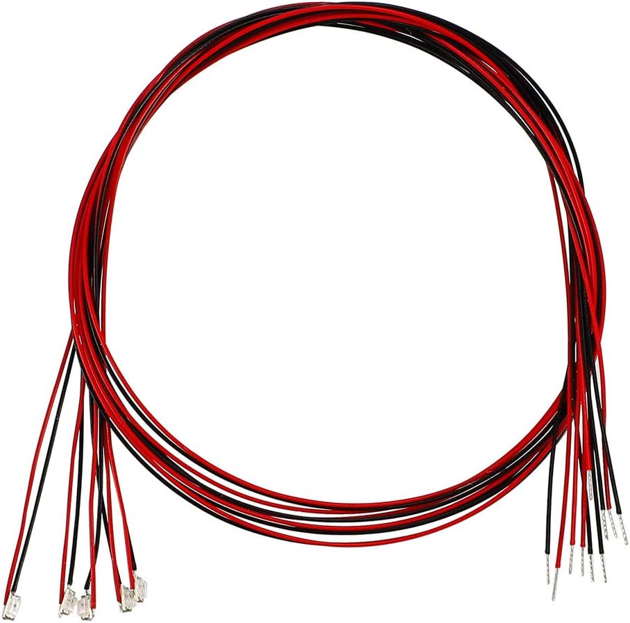
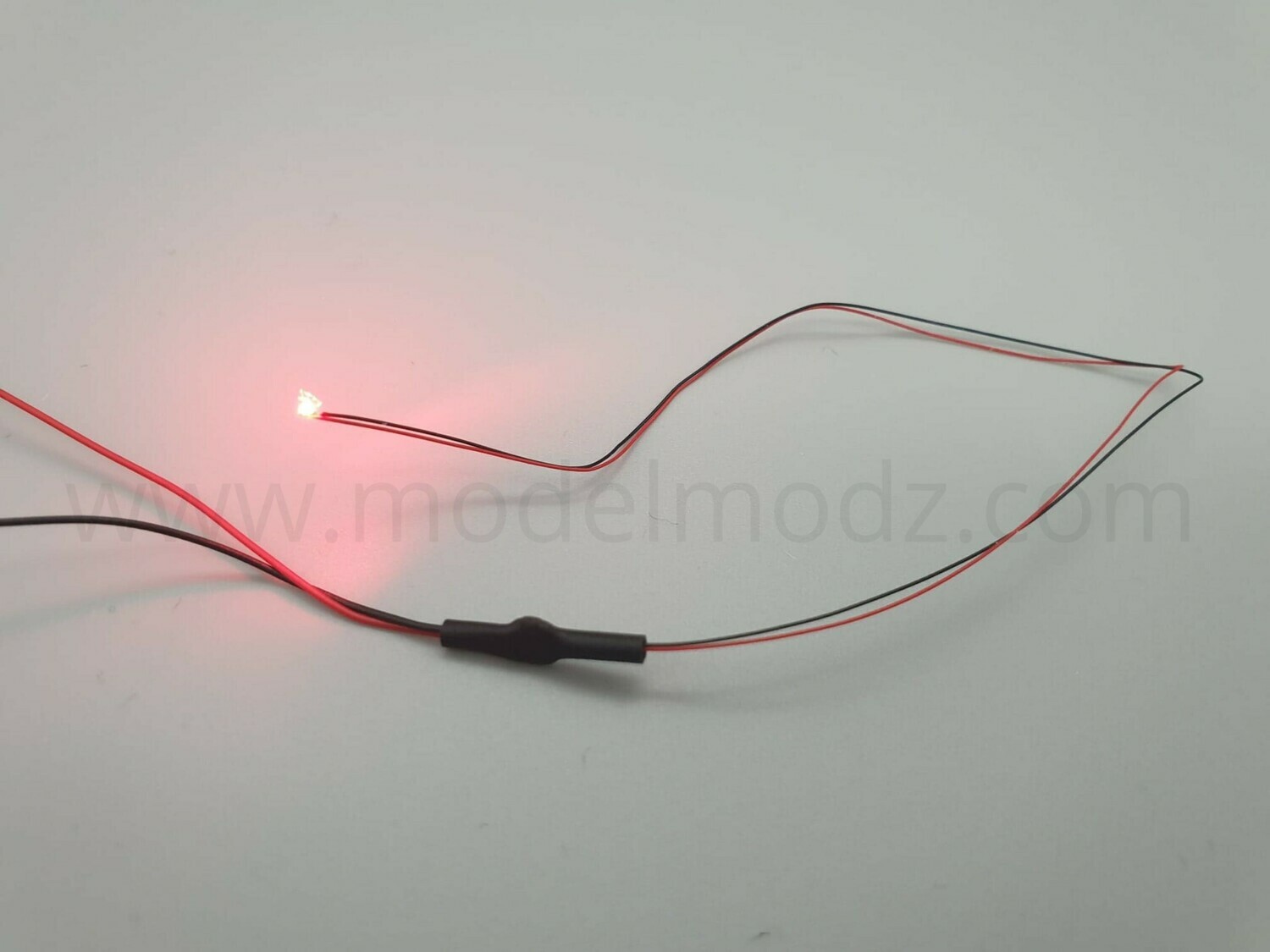
So I'm thinking of switching to the ones with the black and red covered wires you see above. I'd like to give those a try and see if they will work better and be more cooperative and less likely to malfunction or burn out too soon! I also want wires that are more flexible, easier to curve (the Bowerful LEDs had less easily bendable leads.) I would also like to see if they'll work with my Busch crossing signals instead like the Model Modz LEDs did (the Bowerful LEDs wouldn't unless my Busch crossbuck signals were disconnected from the flasher.) The Model Modz LEDs were smaller than I wanted them to be but at least they worked with my Busch signals!

If I could use these and they work with my Busch signals, I'll start using those, and I'll remove the LEDs currently on my gates and replace them with the black and red-covered lead LEDs seen above (I also won't have to order from Micro Modz again like I considered doing and it took more than a month to get LEDs from Model Modz, which is in London, U.K!) And hopefully if I ever get another set of Bachmann dual crossing gates, I can use such LEDs in the crossbuck signals, although I'll have to go with white LEDs, well it won't matter if they're white or LED though the crossbucks come with red lenses. And even after I remove the Bowerful LEDs from the gates, I do want to reuse the resistors they came with to save money, those resistors work real well!

May also need to keep browsing, because what if the LEDs I'm wanting to use don't work either? I already bought LEDs I was dissatisfied with and I don't want to keep investing in LEDs that don't work.

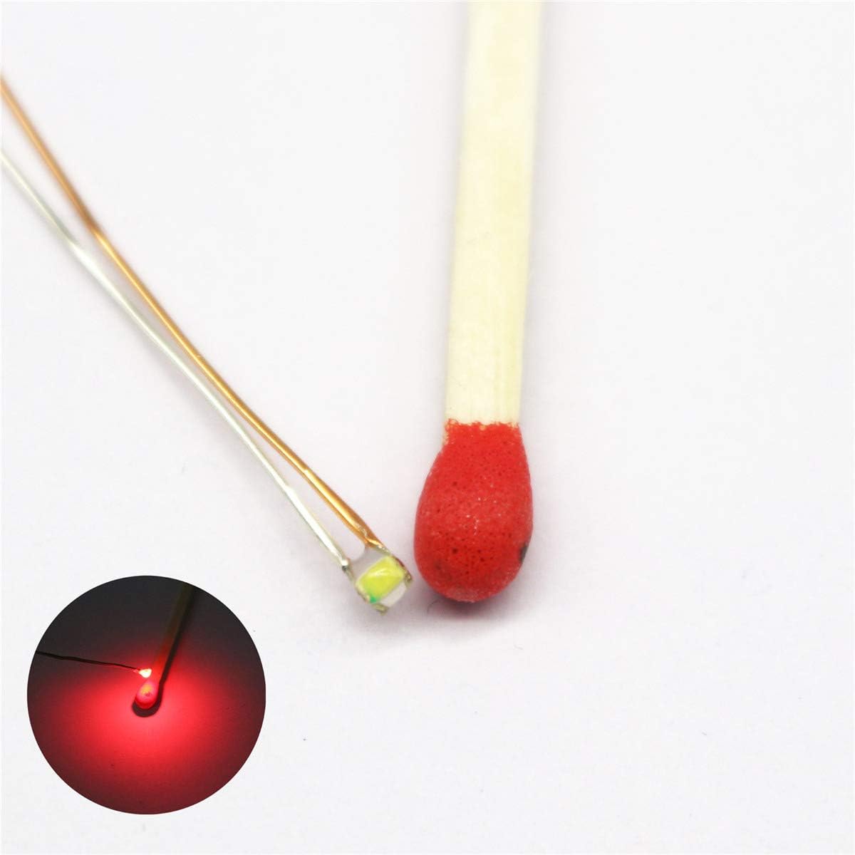
Also open to recommendations, including from other places besides Amazon, but they have to be specifically 0603 LEDs, those I still want to use!


Oh also, I'm planning to try 30 gauge wires, the 28 gauge do work and are thin but they're still a little too wide and I want to use thinner wires, may have to go with 32 gauge even!

Thanks for reading.
 
Not to assume too much, but I suspect your problem has more to do with the installation than the wires themselves. I often use medium guage (e.g. 26AWG) magnet wire when I want to hide a wire or make it fit in a really small space. It's easy to strip because manufacturers switched from enamel to poly insulation years ago, and it can be burned off with a soldering iron instead of scraping. If you use a common ground and resistors on the opposite side of the LED from that, it should be nearly impossible to burn out a LED, even if there are shorts between the wires. When you are working on something as small as your gate, good magnification and work lighting is mandatory. I use a stereo microscope (you can use something less, but I am spoiled from using one at work).

For the flexible part, I suggest "silicone wire". I discovered this stuff recently, it's brilliant! It's very fine stranded wire encased in a super flexible silicone insulator, the result is a wire that bends very easily and can flex many many times before wearing out. You could wire everything on the gate, gluing all the wires solid to the gate, and then use silicone wire to bring the connection through the gate hinge. I'll be blunt - the red/black versions look really clumsy for HO scale. The wires are way too thick, and especially after you paint them to hide the obnoxious colours.

I shun Amazon and get things directly from Asian vendors on AliExpress. I used to use Ebay because the same vendors use it, but I found out the shipping is usually more expensive when buying from there. It can take a month or two to get stuff from there, but you save a ton of cash.

If you post more detailed information about the gate wiring, I can probably help you solve the shorting problem. Perhaps it's the one in your avatar, but I can't see it very well. :)
 
Last edited:
i just buy lots of 100 to 500 leds from china / ebay .. they are dirt cheap, just make sure they are the colour temp you want, and the viewing angle
 
@diesel Hi Diesel!

Well I'm not sure if it's the installation or the wires, maybe it is the installation (I thought you said "insulation").

Now before we go on, is this what you mean by "Magnet Wire?"
July 15, 2021 Busch Signal and Wires.png

These are what the Busch 5934 HO crossing signals use and I have about seven pairs of them (got my first set in 2003!) I don't really like these kinds of wires because the insulation on them is not so easy to peel, which means if the bare part of the wire breaks off, that's it, I cannot use the signal anymore (or so I think) and it's already happened to one of my Busch signal sets! But if I can use a soldering iron to melt off the insulation, that's good because I happened to buy a soldering kit a few months ago but haven't started using it yet!

Something else I don't like about the Busch signals, other than the fact that they're so fragile and only come with two LEDs instead of four even for the rear-facing flashers, is the fact that the wires aren't color-coded, they're all the same. I mean the positive wires (I think those are the positives) go in the middle terminal in the black flasher unit while the other four wires that go to the left and right terminals are the negatives (from what I've recently learned about LED signals.) And if the wires come out of the terminals, it'll be very hard to know which are the positives and which are the negatives and they can go into the wrong terminals and not work and it will be a while before the signals will start working right again, provided the bare part of the wire isn't lost! (I know I can color code them myself by the way!)

I did find this article on Automating and Maintaining Busch signals http://willegal.net/railroad/crossing.htm I also found this webpage https://model-railroad-hobbyist.com/node/33464

But I'm more comfortable using non-magnet wires, I know they're thicker and more obvious but I'm afraid to use magnet wires (if that's what those wires on my Busch signals are called.)

...

Now about my crossing gates, you said you wanted a more detailed information about the gate wiring. Yes it's the one in my avatar but that was before the fake lights were removed and the actual LEDs were added.
Busch Signals and NJI 1172 Gates on Bachmann Crossing.png

A better view of my avatar picture.

Now let me show you the LEDs I ordered and with and without the gate(s) showing
0603 SMD LED 04 (All LEDs).png

These are the Bowerful brand Micro Litz LEDs (without the resistors showing.) And that's a dime in the picture to show how small the LEDs are! I got these in a 25 pack and was planning to get these in a 50-pack before I changed my mind about buying anymore of these. But the next illustration, not mine, will show you the rundown of the LEDs (including the soldering point and other parts)
61vbPmzde4L._AC_SL1200_.jpg

This is pretty much what I'm using https://www.amazon.com/Bowerful-Pre...litz+0603+red+led&qid=1626391373&s=hi&sr=1-28 And although the wires are said to be insulated, they're made of metal so I learned the hard way and don't feel insulated!

Now to show my crossing gates:
0603 SMD LED 06 plus NJI 1172 gate 01.png

The gate before I glued the LEDs on.

The following are the gates after I glued the wires on
July 15, 2021 NJI Gate 1.png


July 15, 2021 NJI Gate 2.png

Showing the front of the gate and the back of the same gate along with the gate's "partner!"

July 15, 2021 NJI Gate 3.png

Showing the gates lit up!

Also, the wires are not within the gate holders though they probably should be.

July 15, 2021 NJI Gate 4 with signals.png

My other set of NJI 1172 crossing gates that are also lit with the Bowerful Micro Litz LEDs. Also shown are one of my sets of Busch crossing signals. These gates I put LEDs on first and these have the wires within the gate holders! But all my gates have the Bowerful Micro Litz LEDs.

Note, the crossing gate lights are on a separate flasher unit than the Busch crossing signals because I tried to put the gate lights in the same flasher unit as the ones that came with the Busch signals but they just won't work together no matter what I do, that's why they're on separate flashers, and that's also why I'm thinking of switching LED brands because another set of LEDs I had did work in the same flasher unit as my Busch signals, the ones from Micro Modz:
1088148239.jpg


The Ultra Nano SMD LEDs did work with the Busch crossing signals but they were just too small for me (they might work better with N scale crossing gates though, although I never had N scale crossing gates or signals!) But they did work inside the Busch crossing signal flasher unit along with the Busch crossbucks though it did dim the LEDs. I'm wondering if it's the type of wiring that kept the 0603 LEDs from working in the Busch flasher unit along with the crossbucks.

Basically the 0603 LEDs wouldn't work along with the Busch crossbuck signals unless the crossbucks were disconnected from the flasher unit, then the gate lights would work!

And I'd take the Busch signals out of the their original flasher unit and transfer them to another flasher unit but again I'm afraid to mess up the Busch signals and I cannot afford to replace the signals right now. I also don't know how to replace the LEDs in the signals although one of the links above tells you how to maintain the signals. In fact I was planning to stop using Busch signals and use NJ International 1095 crossbuck signals so I can wire both the gates and signals to one flasher unit (unfortunately NJ International is out of stock on all its crossing products except its Wig Wags! And I don't use wigwags, they're not my type of signals!) Not even sure how to add resistors to the wires used on the Busch signals without breaking the wires and having to peel off the insulation.

I also admit none of my wires are soldered, be them the LED leads, resistors, or added wires. I plan to solder eventually but for now I'm twist-tying the wires together. I also need to put on heat-shrink tubes or liquid electric tape, which I hope to acquire next month.


I would basically like 0603 LEDs or LEDs the same size as them that are wired like the Model Modz LEDs (with black and red "rubber" insulation that can easily be peeled with a knife or scissors) and that will work with the Busch signals when wired to the flasher unit! If they can work with the Busch signals I won't need to buy more flasher units or buy NJI crossbuck signals or signals from anywhere else!

I hope this helps and this wasn't too confusing. I tend to write long messages!
 

Attachments

  • 0510211628.jpg
    0510211628.jpg
    394.4 KB · Views: 100
  • HO Scale Signal and Gate Demonstration GIF 1.gif
    HO Scale Signal and Gate Demonstration GIF 1.gif
    28.9 KB · Views: 111
Great! Thanks so much for the detailed reply. Yes, that is what I mean by "magnet wire". I can see where your frustration is coming from. That is a lot of wires in a small area. While I'm digesting this tonight, I have one immediate comment. I see that there are three LEDs on each cross arm. It appears as though you have brought six independent wires back from each LED to the hinge(right name?). If they all come on at the same time (i.e. they don't alternate), you can wire them in series and bring back only two wires from each cross arm. I'm sure that would simplify things. The only difference is, you need a slightly different resistor value, which does depend on the power supply voltage. Even if the flashing is like the animated GIF you posted, you can reduce it down to 4 wires from 6 by running a common wire for all 3 LEDs. Even only 3 wires if you can tolerate two of them flashing together alternating with the other one! Technically, you can drive 2 alternating LEDs with only 2 wires, but it requires a dual polarity driver. The somewhat flamboyant technical term "Charlieplexing" applies. With Charlieplexing, you can have 2 LEDs on 2 wires, 6 LEDs on 3 wires. Independently controlled, not just wired together. You also expressed that you needed two flasher boards when only one should be required. I would need a lot more details of the entire wiring system to fix that, but I think perhaps it is possible to drive all the LEDs from one board anyway. More to come...

One big question that will need an answer, is where the resistors are located in the Busch system. In the control unit, or in the crossbucks?
 
Last edited:
I would say the control unit.

Speaking of which, I wish I thought of this when I made that last comment, whether the gate lights have resistors on them or not, they still won't work in the Busch control unit unless the crossbucks are disconnected. I tried with added resistors and without added resistors, nothing!😐

Thanks for your comment so far! I'll need to read it again, maybe over and over to understand it better (actually I'm tired right now so when I'm not tired I'll understand it better!)
 
Try connecting the LEDs in series... I usually speak in schematics but maybe you can follow this...

There are three connecting posts on the Busch. The outer posts appear to be (+) LED drives, and the center is a common return (-). So here is a possible wiring (I will begin with just one LED on the gate to keep it simple):

1. wire from the Busch outside post to the crossbuck
2. wire from the crossbuck to the anode wire of a gate LED
3. wire from the cathode wire of the gate LED to the Busch center post

That should give you a LED on the gate that flashes in unison with one on the crossbuck.
 
Thanks Diesel!

Am curious, do you have Busch crossing signals? And do you light up gate arms too? Just curious.

Thanks for your help! It isn't just for me but for anyone in my situation, at least that's how I like to see it!

I'm still planning to switch LED brands, at least I think that's what I want to do.
 
No, I don't have them. I followed the links above and looked at the Busch manual (which doesn't say nearly enough, IMHO...). I have no gated crossings yet, I may do it sometime but as you know, it's far easier to make a gateless crossing. Use whatever type of LED does the trick.
 
No, I don't have them. I followed the links above and looked at the Busch manual (which doesn't say nearly enough, IMHO...). I have no gated crossings yet, I may do it sometime but as you know, it's far easier to make a gateless crossing. Use whatever type of LED does the trick.

First, thanks for explaining more simply. As someone with autism I need things explained simply and clearly and I like the way you explained it. Yeah I learned the cathodes go in the positive posts while the anodes go in the negative (I got it backwards when I tried, so I reversed the wires and it worked...when I used the ModelModz LEDs!)

I hear you on gateless crossings being easier to install than gated. And I can see why most people who do gated crossings don't put lights on their gates, it's complicated. I mean I wish I could see more HO scaled lighted-arm gates but now I understand why most people don't do them (could also be they're not interested and feel no need to do so.) I also wish more cartoons would show lighted crossing gate arms, some do but many crossing gates in animated shows don't have gate arm lights!

I don't know if I should recommend Busch signals or not. They work great and come with a flasher unit so you don't have to buy separately! But the signals are small and fragile and can break easily, they only come with two LEDs, not four, and the flash rate is quite fast! But these are more convenient to use than other HO signals, which don't come with flasher units that you have to buy separately! Maybe just buy one set of Busch signals and see if you like it if they're still available, check eBay for some or Google it. They are Busch 5934 crossing signals to look them up more easily! But use whatever signal works for you! :)👍
 
I do have a crossing model (it may even be the same one as in your avatar). I bought it used at a RR flea market table. It has the potential for this kind of upgrade but there are too many things I need to finish before I tackle that. I have a home brew circuit ready for that, it's just an Arduino programmed to flash LEDs. Another unfinished project, because I need to also add the train occupancy logic. But I do have a working flasher, you can even select a tungsten filament delay to soften the on/off transitions the way a real tungsten bulb works. So the effort of obtaining a Busch unit would not be worth the effort for me.

I think gate lights are era and road specific. Certainly they didn't always exist. Nowadays just about any crossing has them. I model China Rail so I'd have to go check my location shots to see what they do, I can't remember... have you considered fiber optic strands to convey the lights, or are they not flexible enough?
 
Hi again @diesel

I did try to respond to you hours ago but my message disappeared when my tab automatically reset itself after I went to a new one and tried to come back! :mad: Hate when that happens! Would have started over sooner but was too tired, too stressed and it was late. And I wished I copied and saved it!

As I tried to say (cannot remember everything I said) I'm not sure about fiber optic strands, not sure I know know what they are yet but may look it up. Well I might know, I'm just not sure I do.

All I know is I use wires for my crossing lights be them factory-made signals or lights I add to gates myself, unless those are the FOSs you're talking about. I the wires that come out of the bottom of all my signals and they're all flexible, and wire them to flasher units if they're not already wired to them (I.e. Busch signals.)

When lighting and wiring the gates, I like to make it so that the gate lights are in complete sync with the crossbuck lights (e.g. if the right light on the crossbuck is on, the right light on the gate should also be on; if the left crossbuck light is on, then the middle light on the gate should be on, not left crossbuck light-right (innermost) gate light on and vice-versa. And of course the left (outermost) light on the gate stays on. And because the outermost light stays on, I don't wire that to the flasher unit, unless I should, I wire the tip light directly to the power source. The only problem with that is if the power is on, the tip lights will light up while the rest of the lights are dark, especially if the flasher unit is not powered or any light wires are disconnected.

I don't know if I mentioned this but my crossings, well, signals are not hooked up so that the lights flash on train arrival and turn off when train leaves crossing, I intentionally set my signals to continually flash even when the train isn't present (pretty much "crossing malfunction" mode!😂) I don't use detection units.

More about my crossings you see, the crossing platforms are from Bachmann and from LifeLike Products. I however removed or didn't install the original crossing signals or gates meant for those crossings and put Busch crossing light signals and NJ International gates in their place so that nobody is fooled! One more thing, my gates don't go up or down by themselves, they're manually operated and by the way I play with my trains (on the floor,) it's not possible to automatically lower or raise the gates, but I'm okay with that! All that matters to me are the lights flashing. I don't use bells either.

You got me curious about your crossing gates! If it's alright with you, I'd like to see pictures of them so I'll know what they look like. I mean I might know what they are but since I've never seen your gates, I don't know what they are or look like unless they're Bachmann, LifeLike, Tyco, etc.

On another side note, it is my hope one day that I get a set of Bachmann crossing gates, keeping the original signals and gates in place, this kind:
515wCS-KwPS._AC_SL1500_.jpg

except I want non-EZ track but they don't make non EZ-track anymore and the non-EZ track only come with black and white gates but I want modern red and white as pictured, and I plan to get a set of the black and white on eBay and ask Bachmann again if I can request two red and white gate arm pieces so I can remove the black and white arms and replace them with the red and white, but they said they don't sell those like that. I'll ask again but if they still won't, I'll just have to buy the whole set and end up with redundant parts!

But that's not all I plan to do, I also plan to add LEDs to both the crossbucks and gate arms just like I did with this:
dekzylg-64c137ff-30c4-42e1-a0bc-311b7720317e.png


Wouldn't it seem interesting to have a crossing like that where the lights flash and to watch the gates go up and down while the lights on the gates are flashing on it and as the train is passing by? I'd love to try that one day and if I do, hopefully show you and others! Right now, unless somebody else has done it and shows pictures, it's something I can only imagine right now!😌😎
 
Last edited:
My problem is, I yearn to speak in electronics language, so that I can say in one sentence what would take pages to describe. Someone else who speaks it, would just go "oh, yeah" and run with the description. Perhaps you know such a person, if so you should get them involved. If you're going to try this and still have problems, I'll make a pencil sketch and post it. I'm making a few assumptions here, some may be wrong. If they are right, then I can tell you, "wire the gate LEDs in series with the crossbuck signals". Obviously, the LEDs that you want to be on simultaneously should be in the same series circuit, driven by the Busch unit. Here are my assumptions:

1. The Busch unit has built in current limiting resistors
2. The LEDs all have a fairly low junction voltage drop ~= 1.5V

Since you will have two gate LEDs per phase, the complete circuit would be like:
Busch outer terminal -> crossbuck LED -> north gate LED -> south gate LED -> Busch center terminal
then you would have another identical circuit but for the alternate phase.

As a consequence of the series connection, the resistor voltage will be reduced by about 3V and so all the LEDs will be slightly dimmer. Also if the assumption that the Busch has internal current limiting is true, you should not use any external resistors such as the ones that are supplied with the LEDs.

You can wire the "always on" gate LED to the supply going to the Busch. That way, it will only be on when the gates are activated (by whatever means you choose, simplest would be a toggle switch). Of course, that one would need a resistor.

You should test this to see if it works. Unfortunately the Busch documentation is not clear about where the current limiting resistors are located. However, if you follow the above instructions it should not matter where the resistors are as long as there is one in either the control box or in the crossbuck assembly.

Again, on each arm you only need one ground return so you can use 4 wires instead of 6.

If you want an automatic controller, there are some details here:
Rob Paisley's DIY RR site
 
Last edited:


Back
Top