The Union Pacific Soggy Bottoms Subdivision (HO scale)


Thanks, Lynn! I appreciate it!
I have to use a heavier wire than what Circuitron supplied, as well. I'm using .047" wire. I think if a Tortoise has to be installed after the turnout is already in place that feeding the wire down from above would be much easier than trying to poke it into the throw-bar from below! Especially for us old guys!
I forgot to mention that the turnout coming off the main and the one for the caboose track will both be controlled by the same switch. That way there's no possibility of a train coming off the main to run into a point set against it.
Yep I agree , connecting them together is a good idea . I have an auto throw on one of my reverse loop turnouts and I just realized today that the turnout for the turntable/engine facility/turntable is after my auto throw gap so when an engine comes out I now have to make sure the reverse turnout is in the clear position which as you mentioned getting older, I really like the momentary buttons and position LEDs much better than have to think of a number in the hand controllers.
 
I started laying out the track plan on the control panel. I used 1/2" wide yellow electrical tape. I think I'm going to remove the yellow tape and use 3/4" blue electrical tape. The yellow is letting too much of the dark green show through. I'm going to use 3/4" tape because that's what Menards has! I can get a 66 foot roll of it for $1.99 on sale until tomorrow, so I'm going to run up there and get a few rolls. I installed 4 of the DPDT switches. If I'm going to use different tape, it would be best to do it now before I get too far along! The other 2 switches are out of view to the right.
100_0886.JPG


I did a bit of wiring on the back of the panel. The yellow and black wires come up from the 12 volt bus supplied by the converted computer power supply, which is in the small cabinet on the right. The terminal block on the left will feed any 12 volt accessories, such as Tortoise switch machines, on the left side of the yard. Another will be installed on the right side, but with more terminals as there will be more switch machines on that side.
100_0885.JPG


The small black panel is for my NCE PowerCab. That will be relocated to the front of the control panel. When I fold the panel down the 12 gauge wires fold neatly out of the way.
Back when I had my layout in the other room, I had a spur headed into a "tunnel to nowhere", which I incorporated into a mountain. I saved that mountain, but didn't know what to do with it. I've decided to put it right here:
100_0887.JPG


I'm going to fill in the tunnel, and build up the landscape a bit so it sits level. It would probably be easier to cut away some of the terrain that's already there, but that's the easy way! Can't do that now, can we?
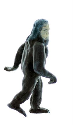
Up on the top of the mountain I made a little cave. I can't find an HO scale Grinch, but I found a Sasquatch!

100_0888.JPG
 
This is looking very good, is the receptacle box on the left that the lite switch is wired to a main power switch?
Yes. That switch controls the power to the layout. Basically what I did was to use a double gang outlet box and use a 12 gauge extension cord as the power in from the wall outlet. Then I extended the hot wire through the light switch. Throwing the switch turns on the outlets, which the computer power supply and the power supply for my NCE PowerCab are plugged into. Everything is grounded so it's all safe. The silver box is where the switch used to be, but when I built the control panel the switch would have been behind the panel. Not very convenient, so I moved the switch.
This is what I did, just extended the hot wire so it's switched.

Then I mounted the box to the layout. Throw one switch and all power to the layout is killed.
Thanks I need to do this.
 
I was going to do the same thing then realized a power strip would accomplish the task. I bought one with a 3' cord so it sits on the floor with everything plugged in, can use my foot to activate. Too easy? Also, surge protection built in.
I use a power strip as well but it’s sitting on a shelf under my layout , I installed a toggle to turn power off/on on the fascia for the accessories power pack for my the ds64’s , but would like to at some point ass curtains off the benchwork to hide the storage.
 
I got the 3 turnouts on the left side of the yard wired up. The two leftmost turnouts are controlled by the same DPDT switch. Since it's basically a crossing I can see no practical reason why one turnout would be set to the straight route and the other to the diverging route. On my layout, a switch in the down position always indicates the straight route, up indicates the diverging route. I also use LED's to indicate route, green for straight, red for diverging.
Here the switches are down, and the LED's green.
100_0891.JPG


The turnouts are aligned for their straight route. All 3 of these are right hand turnouts.
100_0892.JPG


Here the switches are up, the LED's red.
100_0893.JPG


The turnouts are now set for their diverging routes.
100_0894.JPG


Here's a pic of the back of the panel, left side then right side.
100_0889.JPG

100_0890.JPG


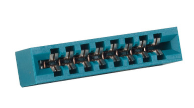
I don't solder wires directly to the Tortoise switch machines. I use edge connectors, and solder the wires to them.

Hmm. MMR used to have 18 of these in stock, now they only have 6. Someone must have bought 12 of them. Wonder who that could have been? :rolleyes:
The wires from the edge connectors then run to terminal blocks. It's much easier to make changes or repairs at the workbench than under the layout!
100_0895.JPG


On the right hand terminal block, you'll notice that the two left top terminals are jumpered, and the two center terminal are jumpered. The top yellow and black wires come from the DPDT switch, and the bottom yellow and black wires go to the crossing turnouts. The two right terminals aren't jumpered, they are for the frogs, power in from the Tortoise, out to the frog. This is how one switch controls two turnouts.
I make notes on the benchwork as to what terminal block controls what power. (SY stands for South Yard). I also give each Tortoise and it's edge connector an ID.
I think the next thing to do is to run the arrival and departure tracks across to the other end of the yard. Then install and wire the turnout and double slip on that end.
 
I got the 3 turnouts on the left side of the yard wired up. The two leftmost turnouts are controlled by the same DPDT switch. Since it's basically a crossing I can see no practical reason why one turnout would be set to the straight route and the other to the diverging route. On my layout, a switch in the down position always indicates the straight route, up indicates the diverging route. I also use LED's to indicate route, green for straight, red for diverging.
Here the switches are down, and the LED's green.
View attachment 162488

The turnouts are aligned for their straight route. All 3 of these are right hand turnouts.
View attachment 162489

Here the switches are up, the LED's red.
View attachment 162490

The turnouts are now set for their diverging routes.
View attachment 162491

Here's a pic of the back of the panel, left side then right side.
View attachment 162492
View attachment 162493

I don't solder wires directly to the Tortoise switch machines. I use edge connectors, and solder the wires to them.

Hmm. MMR used to have 18 of these in stock, now they only have 6. Someone must have bought 12 of them. Wonder who that could have been? :rolleyes:
The wires from the edge connectors then run to terminal blocks. It's much easier to make changes or repairs at the workbench than under the layout!
View attachment 162494

On the right hand terminal block, you'll notice that the two left top terminals are jumpered, and the two center terminal are jumpered. The top yellow and black wires come from the DPDT switch, and the bottom yellow and black wires go to the crossing turnouts. The two right terminals aren't jumpered, they are for the frogs, power in from the Tortoise, out to the frog. This is how one switch controls two turnouts.
I make notes on the benchwork as to what terminal block controls what power. (SY stands for South Yard). I also give each Tortoise and it's edge connector an ID.
I think the next thing to do is to run the arrival and departure tracks across to the other end of the yard. Then install and wire the turnout and double slip on that end.
Nice and neat , I will not show mine lol. I do the same using edge connectors.
 
Hey, all! Been busy with work and home stuff, trying to get some work done on the layout as I'm able.
I was double crossed, by my double crossover! :(
I had it at the foot of the decline, and it worked flawlessly for a long time. Then all of a sudden the locomotives started derailing if the diverging routes were thrown. Messed around with it for a long time, but couldn't get it back to proper operation. I finally decided to move it farther down the line. wondering if the combination of the decline and diverging route was the culprit.
During the removal process, I messed up one the 4 turnouts it's made from, so I had to 'surgically' replace that one. Basically, I swapped the position of the double crossover with one of the Peco small radius turnouts. Now the crossover is closer to the bridge.
100_0004.JPG


100_0005.JPG


The crossover is electrically isolated from the rest of the layout by insulated joiners on all 8 rails. I have all the turnouts in that area throwing in the proper direction, but haven't hooked up the track feeders yet.
I also redid the lift up section. I went from a built up section made of 1x4's and plywood to a single piece of 3/4" plywood braced crosswise with steel angle, and a 3" deep piece of 3/4" plywood.
100_0006.JPG


Alignment is made by two 3/8" machine screws, beveled on one side, which fit into two short sections of steel tube inset into the support on the non-hinge side. Two rare earth magnets pull against two pieces of 1/8" steel plate inset into the bottom of the lift up bridge.
100_0007.JPG


100_0011.JPG


I haven't run track across the lift up bridge because I'm waiting for these to get here:
Currently, the package is at PSC Milton Keynes, which is a parcel sorting center (PSC) in Great Britain. It's been there for the past week. I did a Google search on that center, and what I found was not very encouraging. That place seems to be a bit of black hole in the Royal Mail system. It could be a few weeks before my package leaves the country. And I thought the USPS was slow!

Mater, Luigi, and Guido told me that they missed their friends. Well, not Guido, actually. He never says much. So I got them some companions. From left to right are Doc Hudson (in his Fabulous Hudson Hornet dirt track racing paint scheme), the Sheriff, Fillmore (I'm telling ya, it's a conspiracy, man!), and Sarge.
100_0010.JPG


Mater asked me "When ya gonna let 'em out?" Soon, Mater. Soon.
The little Fiat 500 is HO scale. I know that these are way out of scale, but it's mind over matter. If you don't mind, it don't matter. And I don't mind.
Mater is not a Mattel die-cast vehicle, like the others are. He's a McDonald's Happy Meal toy that I picked up at a train show several years ago. Next Friday, when I get paid, I'm going to order a die-cast Mattel Mater, so he'll be the same scale as the others. Then this one will come live on my computer desk in the man-cave.

Might be time to get working on the yard again. That double slip isn't going to install itself, after all.
 
Currently, the package is at PSC Milton Keynes, which is a parcel sorting center (PSC) in Great Britain. It's been there for the past week. I did a Google search on that center, and what I found was not very encouraging. That place seems to be a bit of black hole in the Royal Mail system. It could be a few weeks before my package leaves the country. And I thought the USPS was slow!
You may have heard that the Royal Mail had a cyber attack some weeks ago and which caused major disruption on overseas packages, as they were unable to track them, this caused the Royal Mail to suspend moving anything outside of the UK.
Although the attack has been resolved, millions of packages were not sent, causing a major backlog which is being processed and sent to their destinations as quickly as possible, if the Royal Mail has it, it will be sent, exactly when, is another story, but I'm sure you will receive it..
 
I've been taking these pictures (and a couple of videos) with a Kodak Easy Share Z91 camera. It does OK for what it is, but I've been wanting to get a better camera for some time now. I got a bonus at work earlier this month, and decided to put the money towards a new camera. I wanted a DSLR (digital single lens reflex) that could also record video.
I'd had my eye on a Canon EOS Rebel T7 that I could buy new locally for $399. Canon makes good cameras, and their EF mount lenses are good quality and plentiful. The downside is that the T7 isn't all that great for video, autofocus doesn't work in video mode (at least that's what I read), and it does not have an input for an external microphone.
I spotted a Nikon D3500 on eBay for $450, but the D3500 didn't really have the features I would have liked, either. So I made it a matter of prayer, because that's who I am and I don't apologize for it, asking God to lead me to the camera I should get.
Monday morning I was watching YouTube and a video came up in my list that looked interesting, so I watched it. A man and his wife were challenged by a viewer to come up with a budget camera outfit for each of them, and see who's outfit took the best pictures and videos. The couple utilized a website for a used photo equipment dealer, keh.com, so I checked out the website, looked at a lot of reviews from different places, and found them to be a reputable company.
So off to https://www.keh.com/ I went. I looked at a number of different cameras, and decided on a Nikon D7000 body which they had graded as EX+, their highest rating. I also bought a Nikon 35-80mm lens graded EX. EX stands for excellent, btw. The YouTuber's have a discount code on their channel, so I used that and got 5% off. I splurged and paid for overnight shipping.
Ordered it Monday morning, the package got here Tuesday morning. FedEx actually came through, for once!
Here's the box, opened but not unpacked:
100_0069.JPG


And the goodies:
100_0070.JPG


That little white spot on the lens cap is the only blemish on this outfit, other than some VERY light scuff marks on the bottom. The battery and charger were included, but I had to buy a USB cable to transfer pics from the camera to the computer.
I could tell this camera had barely been used. It, and the lens, are in pristine condition. It could easily pass for new.
On a digital camera, the shutter has a limited lifespan before it starts to fail and not always open or close completely. Generally, the shutter is good for around 200,000 cycles before it starts to have issues, but that number is just a generality. Another YouTuber made a video detailing how you go about finding what the current shutter count is. Basically, you take a photo and upload it to a website, in this case https://www.camerashuttercount.com/, and they will 'decode' the info on the photo and give you the current shutter count.
Mine came out to be
Shutter count.jpg


One thousand nine hundred fifty six! 1% of this models expected shutter life! As I suspected, this camera has barely been used! That shutter will probably outlive me!
How much did all this cost me? Purchase price, discount, tax, and shipping came out to $349.12! I think I got a good deal! Thanks, God!
It did not come with a manual, but I found it on Nikon's website for download. I was also pleased to discover that a "For Dummies" manual has been written for this camera. I have one coming from Washington state. For those not familiar with them, the "For Dummies" series of books https://www.dummies.com/ takes a subject and breaks it down into plain, easy to understand concepts and language. Perfect for simpletons like me! I also ordered a couple of screen protectors for the LCD screen on the back of the camera. I got the clear acrylic style that snap on to the body, rather than the plain sheet style like we use on our cell phones.
I plan to use this camera to take photos (and hopefully more videos) of my layout and projects. It's going to take some time to learn the features of this camera, though. I used to own a Minolta X700, and have really missed having an SLR with interchangeable lenses. I've wanted a DSLR for a long time, now I have one!
Let the fun begin!
 
I've been playing around with my new camera. It's definitely going to be a learning curve! The local community college offers continuing education (non-credit) classes in a variety of subjects several times a year. One of them is photography. I think next fall when they have their next round of classes I'm going to sign up for one.
I took some photos of the 4014 approaching the bridge. These were all taken with the overhead fluorescent lights on. I don't have any stand alone lights, going to have to get some.
This photo was taken in shutter priority mode. Shutter speed 1/30 of a second (I used a tripod), auto ISO of 1250, and aperture of 4.14.
DSC_2888.JPG


I played around with the photo in Irfanview, a graphics editing program available for free from https://www.irfanview.com/. It doesn't have all the bells and whistles of a program such as Lightroom or Photoshop, but for an average shmoe like me it does fine. Some tweaking of the brightness, contrast, and colors produced this:
Retouched 4014.jpg


I think the original just looks a bit 'harsh'. The wheels on the tender kind of got lost, and the sky looks a bit dull. The retouched photo looks more pleasing to my eye. The sky looks more natural, and the tender wheels stand out much better.
The original image was taken without the camera's flash. This one was taken with the flash.
DSC_2889.JPG


The tender wheels stand out better, but personally I still like the retouched picture better.
I need to delve into the manual and see how to compensate for fluorescent lights. I know there's a way, and I read it, but I don't remember what it was. I'm still a bit overwhelmed.
 
Well, this is the last day of my vacation. :( Those two weeks went by fast! I did get some work done on the cars, and I got some things done around the house, as well.
On the layout, I got the double crossover all wired up. Had to redo that control panel because I moved things around. All good, now, though!
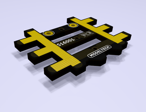
I got the track laid down and wired on the liftgate. I tried to use the Rail Aligners I bought from England, but just couldn't seem to get them to work right on the liftgate. ModelTech, the manufacturer, recommends slightly overlapping onto the fixed portion when using them on a lifting section. I did that but just couldn't get them to work properly, so in the end I didn't use them.
I've been mocking up the end of the layout where the meat packing plant/stock yard will be. I also plan to put the salvage yard on that side. The packing plant/stock yard takes up a fair bit of real estate. After trying several different arrangements, this is what I settled on. The UP #4439 0-6-0 will handle switching duties for this end of the layout. Everything except for the inner and outer main lines are simply lying on the layout, nothing is installed or wired.
The left most track is the outer main line, next to it is the inner main line. Just before the furthest turnout on the inner main is a Kadee electromagnet uncoupler installed below the track. The 4439 is on its refueling track. The tank car next to it represents a tank whcih be permanently installed on a foundation, because the 4439 is an oil burner. I plan to install a water standpipe there as well. On the short straight track between the two turnouts behind the 4439 I'm going to install an under-track magnetic uncoupler. The switcher pocket extends back onto the liftgate.
DSC_2902.JPG


The way this will work is: When the 4439 gets word that the local is bringing some cars that need to be go the industries, or the local needs to pick up some cars from the industries, the 4439 will back down into the pocket. The local will pull forward until all the cars going to the industries have passed the electromagnet. Then the inbound cars will be uncoupled, the local will pull forward past the turnout, the turnout will be thrown and the local will back the cars into 'runaround/pocket' until all inbound cars have passed the uncoupling magnet. The local will uncouple from the inbound cars and pull back out onto the inner main. The turnout will be thrown and the local will re-couple with the rest of its train.
Now the 4439 will couple onto the inbound cars and complete its switching tasks.
Here's a view looking down the switcher pocket.
DSC_2903.JPG


Here's a pic of the back of the packing plant. As originally designed by Walthers, the cattle chute up to the kill floor was supposed to come from the other side of the building. I built this kit a to fit the previous incarnation of my layout, so I had to move the chute to the other side. Here's a link to that build thread: https://modelrailroadforums.com/for...ers-champion-packing-plant.29128/#post-405777
DSC_2904.JPG


The stockyard (Another Walthers kit) is at the bottom of the cattle chute.
Here's the front side. There are 3 tracks in front of the packing plant. The farthest goes to the packing plant loading dock, the middle track goes to the stockyard, and the closest track is for car storage.
DSC_2905.JPG


My friends are trying to let me know I should be focusing my efforts on the other side of the layout. Have you ever seen such a motley bunch in your life?
Here's the salvage yard. The far track is working track, the closest is for storage.
DSC_2906.JPG


Between the salvage yard and the edge of the layout will be part of the town.
 
I tried to use the Rail Aligners I bought from England, but just couldn't seem to get them to work right on the liftgate. ModelTech, the manufacturer, recommends slightly overlapping onto the fixed portion when using them on a lifting section. I did that but just couldn't get them to work properly,
What was the issue, they wouldn't line up correctly ?


Back
Top