Newbie question on DCC


I have one DCC ready (two actually as it’s an F7A and B unit with both being motorized). I just ordered a couple of Digitrax decoders last night. The other loco is an old totally analog steamer unit which still runs fine on DC, but it’s definitely not a current day engine. It’s a relic from ages ago and deserves its place in a display case.
 
I have one DCC ready (two actually as it’s an F7A and B unit with both being motorized). I just ordered a couple of Digitrax decoders last night. The other loco is an old totally analog steamer unit which still runs fine on DC, but it’s definitely not a current day engine. It’s a relic from ages ago and deserves its place in a display case.
Enjoy programming those in, play around with the CV's, but make sure you write down what CV's you change and the setting you used, if you get it wrong there is always factory reset, apart from 2 or 4 digit addressing, I don't change the CV's, my brain just doesn't understand them :D

No steamer belongs in a showcase, wire a decoder in (or not) but run it, an older model is noisier sure, but with a little TLC ? You'd be surprised what those older loco's can pull.
 
BTW, new question for anyone who wants to chime in. I just ran my first two analog Locos on my new DCC controlled mainline. I was able to get them to run, however, even at 99% speed, they ran kind of slow and haltingly.
Is this simply 1 loco on channel 0? The "DC" works by the command station extending one pulse for an extra long time. That is, the bi-polar DCC signal is still there but instead of a nice steady shift from positive to negative, the channel 0 pulse stays "on" to the one polarity long enough to be sensed as a voltage on the rail. It can only stay on so long though because DCC has other things it has to do. The hesitation/haltingly part is when the signal has to be used for real DCC commands, the greater the DCC load (number of things it has to communicate to) the more intermittently it can provide that one long pulse for the DC motors.

Is there a way to increase voltage from the command station/booster?
Most DCC systems have a way to change the voltage to the track. Usually from 13.5v to 17v. Some are software buy my Lenz has a physical jumper.
However none of that would necessarily equate to a speed increase of the locos as there are voltage regulators in the decoders. And a final note, our club set ours to 17V because that matched the old Railcommand system we had been using. Turned out to be too high for things without decoders. We melted down several locomotive shells, passenger cars, and caboose that had standard incandescent lighting in them. Learning from that. I run my DCC systems at 14v, and treat all lighting incandescent or LED (resistance computations) as if the voltage was 16v. That gives a nice cushion.
 
Last edited:
Enjoy programming those in, play around with the CV's, but make sure you write down what CV's you change and the setting you used, if you get it wrong there is always factory reset, apart from 2 or 4 digit addressing, I don't change the CV's, my brain just doesn't understand them :D

No steamer belongs in a showcase, wire a decoder in (or not) but run it, an older model is noisier sure, but with a little TLC ? You'd be surprised what those older loco's can pull.
Thanks again for your helpfulness Smudge! Blessings bud! 🙏😊👍✅
 
Is this simply 1 loco on channel 0? The "DC" works by the command station extending one pulse for an extra long time. That is, the bi-polar DCC signal is still there but instead of a nice steady shift from positive to negative, the channel 0 pulse stays "on" to the one polarity long enough to be sensed as a voltage on the rail. It can only stay on so long though because DCC has other things it has to do. The hesitation/haltingly part is when the signal has to be used for real DCC commands, the greater the DCC load (number of things it has to communicate to) the more intermittently it can provide that one long pulse for the DC motors.


Most DCC systems have a way to change the voltage to the track. Usually from 13.5v to 17v. Some are software buy my Lenz has a physical jumper.
However none of that would necessarily equate to a speed increase of the locos as there are voltage regulators in the decoders. And a final note, our club set ours to 17V because that matched the old Railcommand system we had been using. Turned out to be too high for things without decoders. We melted down several locomotive shells, passenger cars, and caboose that had standard incandescent lighting in them. Learning from that. I run my DCC systems at 14v, and treat all lighting incandescent or LED (resistance computations) as if the voltage was 16v. That gives a nice cushion.
Thanks Iron! Very much appreciate the thoughts and guidance! I’ll keep it all in mind. I know the Digitrax manual on my Evolution system discusses how to adjust voltage. I need to look at it a bit more closely. I get the new decoders for my F7s by Friday. I’ll let you all know how it goes. 🙏🤞
 
Ok, the latest: got my decoders and the F7A unit runs fine on DCC with good, consistent throttle response. Here’s my latest dilemma . . . I bought two Digitrax PM74 units which are designed to handle short circuits ( will shut down the respective section) and/or also handle AR situations. But no matter how hard I try, I can’t get them to configure for handling AR. I’ve been on with Digitrax tech support, and though they’ve given step by step instructions, I still can’t get it to configure, so when my loco hits the gap where reversing the polarity is required, the layout just shuts down. The instruction manuals accompanying Digitrax products are written very poorly IMHO, and they seem to expect a lot of ingrained DCC knowledge, it seems. Soooo . . . anyone out there have any Digitrax PM74 experience? It is a relatively new product, but I thought I’d ask.
On a slightly different topic, has anyone got experience with these cheapie little Atlas switch control boxes (for solenoid turnouts)? I’m trying to get one of these to control two turnouts which come together to form a crossover, but the box will only seem to control one switch at a time! If I try to put both switches together on the one control box, neither one wants to work correctly and all I get is a buzzing sound when I push the button down. Anyone wanna tell me what I’m doing wrong on this? Thanks! Mike
I can't help with the PM74 as I have no experience with them, as for the turnouts, sounds like their not getting enough power to throw the switches, are you using a CDU ?(Capacitor Discharge Unit)
 
Last edited:
I can't help with the PM74 as I have no experience with them, as for the turnouts, sounds like their not getting enough power to throw the switches, are you using a CDU ?(Capacitor Discharge Unit)
No Smudge, I’m not using a CDU. Don’t know anything about them. I’m simply wiring up the crossover exactly as the Atlas layout book tells me which is to use one switch control box to control both turnouts. Are CDUs easy to hook up? Your point is well taken, however, about there possibly not being enough current to activate both switches at the same time from one switch control box, as when I drop down to just one switch at a time from the one control box, the one switch hooked up works fine. Both switch solenoid motors are working fine when each is just by itself. It’s only when I try to control two at the same time that nothing seems to work.
 
No Smudge, I’m not using a CDU. Don’t know anything about them. I’m simply wiring up the crossover exactly as the Atlas layout book tells me which is to use one switch control box to control both turnouts. Are CDUs easy to hook up? Your point is well taken, however, about there possibly not being enough current to activate both switches at the same time from one switch control box, as when I drop down to just one switch at a time from the one control box, the one switch hooked up works fine. Both switch solenoid motors are working fine when each is just by itself. It’s only when I try to control two at the same time that nothing seems to work.
Yeah, there designed for 1:1 operation, so it's no wonder, it's no biggie tho, a CDU is easy to rig up, 10 mins maybe, depends how you wired the control box up, if you've done the power to the switches daisy chain style, it should take you less than 5mins to install.
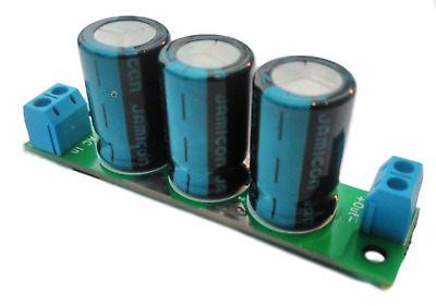
You need something like this, and you may also need a wall wart it depends on how your powering the switches at the moment.


Your local LHS should have, if not fleBay $5-$10
 
Last edited:
All a CDU does is store power till you need it, when you flip the turnout switch it provides a momentary extra boost to snap the switch over, I've got a similar one, and switched 3 double sets of t/o's (or 6 t/o's) simultaneously no problem,
and they work with any switch.
 
Yeah, there designed for 1:1 operation, so it's no wonder, it's no biggie tho, a CDU is easy to rig up, 10 mins maybe, depends how you wired the control box up, if you've done the power to the switches daisy chain style, it should take you less than 5mins to install.
You need something like this, and you may also need a wall wart it depends on how your powering the switches at the moment.


Your local LHS should have, if not fleBay $5-$10
Thanks greatly Smudge! I’ll check it out.


Back
Top