Looking for input from all of the layout designing brain geniuses here


Mike_Arnold

Newbie Modeler
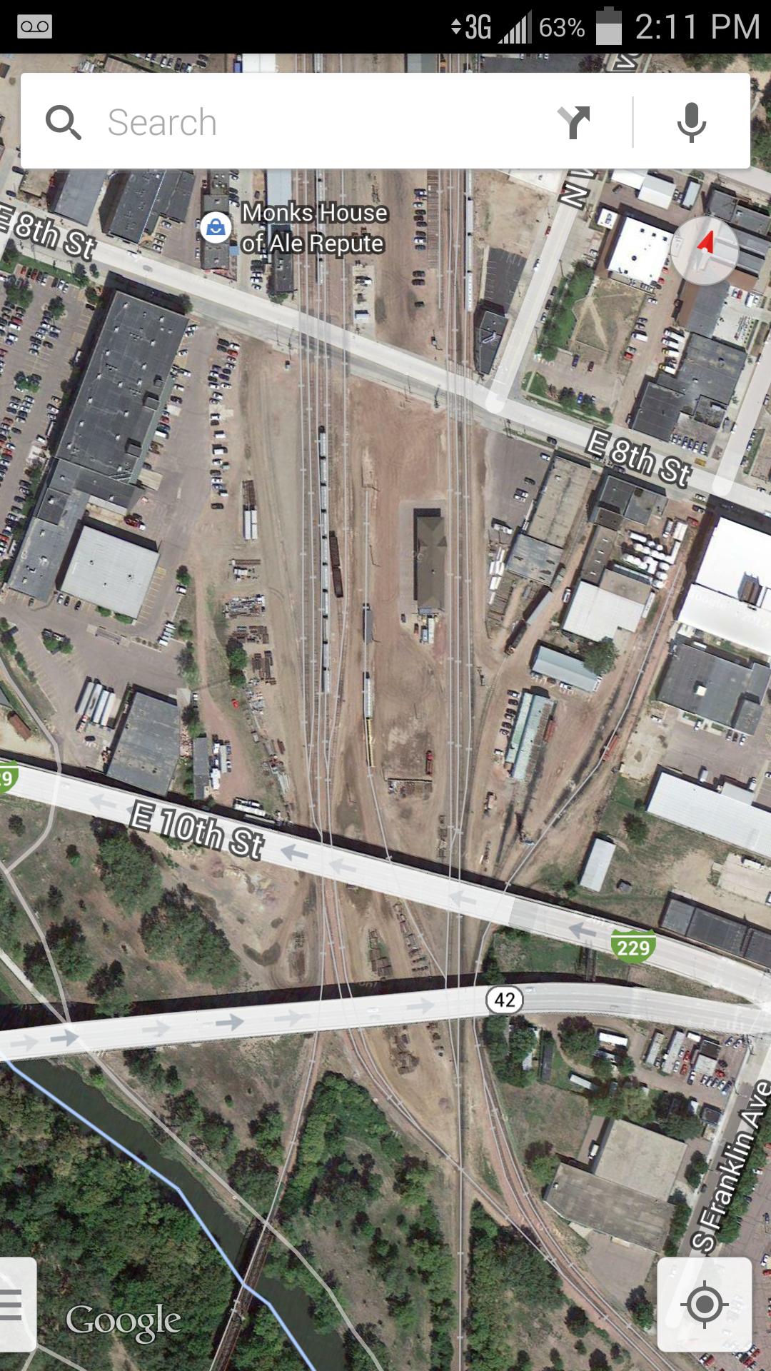
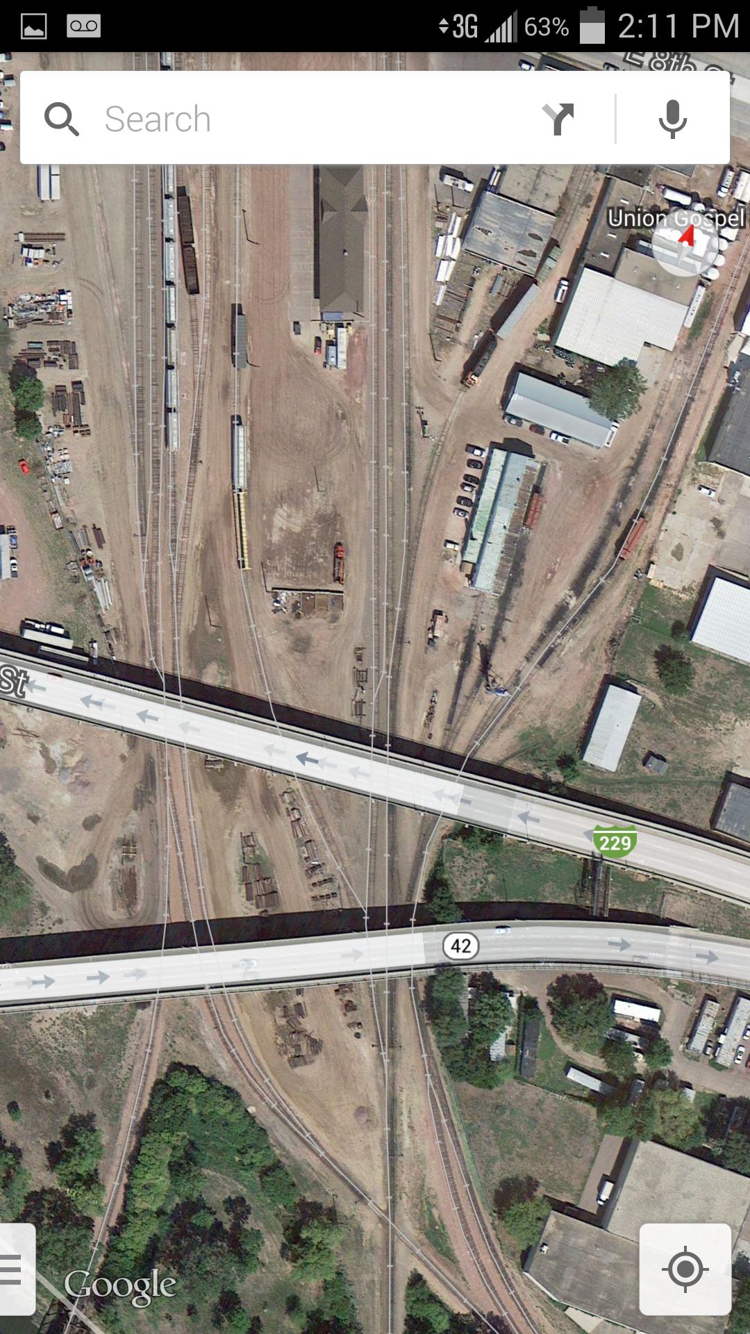
Okay, long story short I have a friend who is going to begin modeling the Ellis and Eastern RR (Sioux Falls, SD). They are a privately owned RR and have 5 engines so it wouldn't be too hard to model all 5 on one small layout. It interchanges with BNSF to the south east. If you take a look on Google maps you can see their engine house is next to the quarry. And there are various industries along the line West of the Wye. The scrap yard is a definite must, and maybe 2-3 of those various industries. We'd also like to model the interchange as this would be for staging most likely. I'll post the hastily made track plan I came up with last night, but also have the questions:

1) What would you change in order to more effectively model this railroad?

2) Can you do it using less space? Looking for Point to Point so no dogbone is needed.

m6Yos0n.jpg


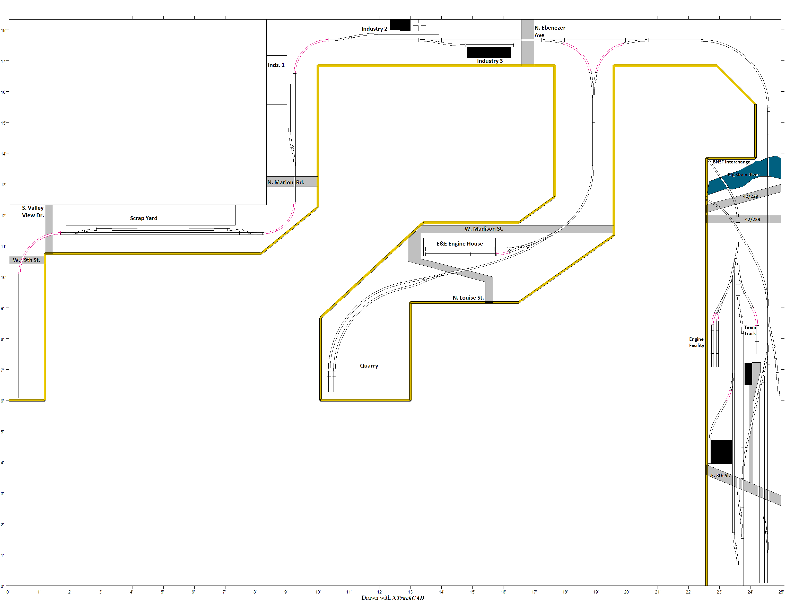
Here's the download link for the xtrakcad file.

http://www.filehosting.org/file/details/457790/Ellis and Eastern.xtc

Any input is appreciated!
 
id probably move the turnout for industry 2 to in between the turnout for industry 3 and ebenezer ave, and make it a right turnout(keep the industry2 where it sits). sould eliminate the "s" curve there, and would make a little operational challenge.

you could do it in less space, but i wouldnt.
 
I like the track plan-and the best part is that it can be adapted to what the owner wants to do. One question-what is the possible use of the track below West 9th Street? I can see having two more industries in there, or one larger one with multiple sidings. It could be the interchange trackage too, with South Valley View Drive serving as a sort of scenic view block.

I've been to Sioux Falls-what era is being considered? If it's backdated enough, the meatpacking industry could be represented, too. I know there is still some meatpacking, but alas, not like it used to be.
 
Mike
Overall your plan is a very good one but neither the E&E nor the BNSF yard looked like they could be worked very easily. The leads on the bottom of the yards look too short to be useable. Also there would be too many movements required to go between the two yards. Take a look at my version to see to get some ideas on how the yards might be improved. Had to do the revisions in Picasa so they are kind of crude. Think of them as being diagrammatic so the revisions are not "drawn to scale".

EE & BNSF YARDS - REVISED.jpg
 
I'll take a look and see if I can make some changes but I wanted to make sure if you looked at the yard that you could tell it was the yard from the town. If you look here you'll see some distinct features I added in when originally making it.
J1ZQwxo.jpg

pCDOurq.jpg


Because it really is two separate yards and not one large yard was my reasoning for doing what I did. I'm not sure if he has room to extend it further a foot or not to make the run around a bit better. The crossover at the lead is really distinct too along with the double overpasses.
 
I'll take a look and see if I can make some changes but I wanted to make sure if you looked at the yard that you could tell it was the yard from the town.

Because it really is two separate yards and not one large yard was my reasoning for doing what I did.
i can understand that you want to accurately model a portion of a real railroad ... but why model a portion that is virtually inaccessible to the rest of your model railroad? wouldn't it fit better to only model the one (west) yard?

won't is be very difficult to move cars between the two yards?
 
You'll have to do ALOT of "selective compression" to be able to squeeze all that trackage in the the room you have for your yard both in length & width.
 
Last edited by a moderator:
You'll have to do ALOT of "selective compression" to be able to squeeze all that trackage in the the room you have for your yard both in length & width.

Yes this we know, I'm thinking he will have to pick one or two things that he wants to model yard wise, maybe just have a single track for the BNSF interchange but do all of the switching on the E&E yard. I do think that the two bridges over the river and double overpasses would be a very cool scene to model personally.
 
Mike
Don't know how you came up w/ your original track plan, but try making a freehand drawing first then try to put that in your CAD program. One problem w/ CAD though is you have to use whatever switches that are in the program which "forces" you plan to come out their way want & not the way you want your tracks to go.
 
Take a look at my version to see to get some ideas on how the yards might be improved.
That might be an improvement in the yard but it totally looses the feeling of the prototype the author is trying to capture. I like the original plan much better. This size of a layout does not need a large yard for operations so one would only include something bigger just for the sake of having a larger yard.

i can understand that you want to accurately model a portion of a real railroad ... but why model a portion that is virtually inaccessible to the rest of your model railroad?
Because it looks good? I've designed many layouts with less operable trackage than this just because it fits the scheme. Make too many compromises and suddenly the model isn't a model anymore but an imagination or fantasy.

I have a friend who is going to begin modeling the Ellis and Eastern RR (Sioux Falls, SD).
1) What would you change in order to more effectively model this railroad?
2) Can you do it using less space? Looking for Point to Point so no dogbone is needed.
Having now examined the satellite maps for quite a while, and finally understanding that north is to the bottom of your diagram (at least for the yard), I think you have done a fantastic job. I don't know that my suggestions would make it any better. But since you asked....
1. I would work harder to fit in the only facing point industry on this leg of the railroad, The CENEX AutoForce Lubricants place. Even if that costs the current Industry #3. But in conjunction with #2 below you might not loose anything.
2. I would ignore the large western tail ( your track on the leftmost edge ) unless there is some industry there I'm not seeing. Anyway then you could shift all the industries one position and fit one more in. That is move the scrap yard to that last island, move industry 1, 2, & 3 where 1 is. and add the curved Lubricants plant to jutting out a bit from where industry 3 currently is. OR just industry 1 to where scrap is. and put 2 & 3 where 1 currently is.
 
Last edited by a moderator:
Just another couple comments.
1. I noticed that the satellite map you posted caught a BNSF caboose in service! What a bonus.
2. The cement plant on west 9th has a Trackmobile. Another interesting thing to model.
 
do you actually intend on using both yards in an operating session? i could see using it as a place to put some cars, and having a bnsf switcher use it to move cars around, just work a yard that really goes nowhere. i like the original plan, with it being a short line you really do not need that big of a yard.
 
There were two glass making places on the LAJ Ry that received 8-10 2 bay covered hoppers of silica sand plus 1-2 w/ lime per day. The hoppers were spotted on a siding (not a spur). The 1st car to be unloaded was put on the unloading spot. The cars were advanced by gravity & using of hand brakes. Would imagine cement hoppers would be loaded/unloaded the same way


Back
Top