Boy, we have ended up with two pages on this post! Well Blacklash, I have just tested your post of the Kato hookup with the LEDs first and then the switch after using a pushbutton switch. Works great. Now I just need to clean up the wires and I think that I will have a setup that does almost all of what I want. Thanks to all for giving your thoughts. Harlan

You are using an out of date browser. It may not display this or other websites correctly.
You should upgrade or use an alternative browser.
You should upgrade or use an alternative browser.
LED Wiring
- Thread starter Royalhaw
- Start date
ModelRailroadForums.com is a free Model Railroad Discussion Forum and photo gallery. We cover all scales and sizes of model railroads. Online since 2002, it's one of the oldest and largest model railroad forums on the web. Whether you're a master model railroader or just getting started, you'll find something of interest here.
Harlan,
It should not matter if you apply your input power to the centre two terminals, or the outer two terminals, both will give the same result, an output that reverses polarity when the switch is changed...
Gents, with the diagrams that I provided, I tried to give you a cheap and easy to understand solution the problem.. I believe that I did this..
As for a way of doing this work with only one pushbutton, and a relay under the layout... Well, you are going to need a bistable "flip/flop" relay that will change state when it receives a single pulse, like what you would get from pressing a single Normally Open (N/O) pushbutton once, such as this http://www.te.com/catalog/bin/TE.Connect?C=1&M=BYPN&PID=114433&PN=RT424A05#features ..You would then still have to work out how to send a single short pulse to the turnout so it will change direction, AFTER the relay has changed...
All mine from start to finish.
If the Kato is a dc motor that slides, it will probably work. I'd have to know the electrical details. Mine works with several varieties of dual coil sliders, including under table.
Nope. Heat in any resistance is I squared R. That would be less than 20mA LED current squared times motor resistance. That would be .008 watts more or less typically.
The advantage of my circuit is I can run just two current paths to power any turnout, it tells me if a wire or coil is open (LED won't light if open), and a third conductor can power an indicator at all turnout entrance points. I put little home made dwarfs so I can see which way the toggle is set at the turnout. The dwarfs are wired red common, with greens on the external feed. They are opposite colors, and invert with polarity change of the toggle.
Since I use two LED's in each dwarf, I have to add diodes across the LED's. One diode gets a series resistor to take the red down a notch, because the red gets too bright by eye compared to green.
I actually use the outer rail as a common rail all through my layout (except at a Wye where both rails float) so I only run ONE wire to my turnouts and tie the common rail to the return. This way two wires in my wiring run all dwarfs and the sider at any turnout.
Right now I'm using it to run my signal bridges, but I hope to integrate my IR sensors so it is a dual control system.
Just don't sell it.")
A bridge rectifier with a CT transformer will have a dual polarity output. It is actually two full wave rectifiers in one package when used that way.
The only thing about the supply is it needs to be fairly stiff. It has to handle the discharge current with sagging more than a few volts in the transition. This can be handled either with energy storage in a large filter cap, or a regulator. I opted to patch in negative and positive regulators plus small energy storage caps of 4,700uF each on the negative and positive buss.
I switch my cross overs with a single toggle. If they get sluggish, increase the cap size.
Breadboard first. Unfortunately boards wind up about $30 bucks or so each in low quantities.
Look at 4PCB.com
Of course one single board handles 16 turnouts, the toggles fit two ways, and the board can be sliced into separate parts with four on a slice.
I just buy the boards because my time to breadboard is more expensive than board cost.
Yes. One toggle runs one setup. I have two turnouts on one switch at crossovers, or where they must track.
That's right. SPDT.
Because it is a dual supply with + and -. The toggle picks either + or - to feed the system.
I lay the boards out on computer. I send the .gbr files to Advanced Circuits where they make a quality solder mask, silk screen labeled board with all plate throughs and tinning.
We used to etch here, but it takes about two hours a board for prototypes and I have to use push in eyelets instead of plate throughs.
I have to balance internal labor against what a professional board house can do. Of course I assemble the boards here.
The process is I lay the boards out on computer, send off the files, get boards back, and then I build them.
Tom
S1 is a single pole double throw toggle.
Yes, in my system I used a bridge rectifier type supply with the center tap of the transformer as the common. This gives dual voltages. The supply is laid out on the PC board. All parts, even the transformer, mount on the board.
DL1 and 2 are shown as incandescent lamps, but can also be bipolar or conventional LED's with the addition of a series resistor. They are indicators only, unnecessary for function.
C1 does two things. It limits the time high current is applied to the solenoid coils to the charging time of the capacitor, and it also doubles initial voltage. This makes the action very positive without causing any damaging temperature rise in the coils.
The points move rapidly and firmly, and can be instantly reversed with this system (no waiting for recharge)!
This system takes either two stiff supplies or one dual polarity supply. My board has the transformer and supply on the board, so the board runs off either 120 VAC or 12/24 AC by bridging the secondary with a low voltage AC source.
The direction indicator works because it indicates "charge" direction across the capacitor. The charge direction varies of course with the supply polarity.
The charge/discharge path for C1 is dependent on the wiring to the turnout and the turnout, so if anything opens the indicators will not work.
Since LED path resistance is much higher than turnout path resistance, the toggle indicator LED's do not affect operation.

Affiliate Disclosure: We may receive a commision from some of the links and ads shown on this website (Learn More Here)
OK gentelmen. Changes. Backlash on your "Kato turnout diagram" you show the main DC power being attached to the center posts of the DPDT. In fact the DC main power wires are attached to one set of end terminals. Then jumpers are put on the DPDT from that set of terminals to the other set of outside termnals but these jumpers are reversed. Than the wires to the LEDs and turnout are attached to the center set of terminals. Thus when the DPDT is in the left position that set of terminals send DC to the center terminals in a +/- mode and when the DPDT is switched the center terminals they get DC current in a -/+ mode. This gives the reversal of current needed to change the LEDs color and to activate the turnout motor after the push button is activated. Must remember to have the pushbutton on the side between the DPDT and the turnout. The DPDT is the thing that is changing the polarity of the power to both the LEDs and the turnout. This works great. Have tested. Thanks for everyones help all going fine. Harlan
OK gentelmen. Changes. Backlash on your "Kato turnout diagram" you show the main DC power being attached to the center posts of the DPDT. In fact the DC main power wires are attached to one set of end terminals. Then jumpers are put on the DPDT from that set of terminals to the other set of outside termnals but these jumpers are reversed.
Harlan,
It should not matter if you apply your input power to the centre two terminals, or the outer two terminals, both will give the same result, an output that reverses polarity when the switch is changed...
Gents, with the diagrams that I provided, I tried to give you a cheap and easy to understand solution the problem.. I believe that I did this..
As for a way of doing this work with only one pushbutton, and a relay under the layout... Well, you are going to need a bistable "flip/flop" relay that will change state when it receives a single pulse, like what you would get from pressing a single Normally Open (N/O) pushbutton once, such as this http://www.te.com/catalog/bin/TE.Connect?C=1&M=BYPN&PID=114433&PN=RT424A05#features ..You would then still have to work out how to send a single short pulse to the turnout so it will change direction, AFTER the relay has changed...
This is what I use. Works perfectly for all the turnouts I have tested:
http://www.w8ji.com/Model%20train%20layout%20wiring.htm
I run my signal lights and power control relays from this.
http://www.w8ji.com/Model%20train%20layout%20wiring.htm
I run my signal lights and power control relays from this.
Hi TomR..
Is that your work and or design?? (great work if it is..)
Im assuming that these are Atlas twin coil turnouts.??.... I suppose that it would not be that difficult to convert it to suit the Kato single coil Turnouts.. (wire the single coil turnout in place of the twin coils, and leave out the diodes..?)
Do the magnetic coils in the turnouts get warm/hot..?? Looking at the circuit it seems that either one of the coils has at least 15mA flowing through it at any given time.. (return path for the indicating LED's flows throught the turnout coil..)
Look, I'm not having a go at your work, I'm just curious that's all..
Last edited by a moderator:
Hi TomR..
Is that your work and or design?? (great work if it is..)
..
All mine from start to finish.
Im assuming that these are Atlas twin coil turnouts.??.... I suppose that it would not be that difficult to convert it to suit the Kato single coil Turnouts.. (wire the single coil turnout in place of the twin coils, and leave out the diodes..?)
If the Kato is a dc motor that slides, it will probably work. I'd have to know the electrical details. Mine works with several varieties of dual coil sliders, including under table.
Do the magnetic coils in the turnouts get warm/hot..?? Looking at the circuit it seems that either one of the coils has at least 15mA flowing through it at any given time.. (return path for the indicating LED's flows through the turnout coil..)
Nope. Heat in any resistance is I squared R. That would be less than 20mA LED current squared times motor resistance. That would be .008 watts more or less typically.
The advantage of my circuit is I can run just two current paths to power any turnout, it tells me if a wire or coil is open (LED won't light if open), and a third conductor can power an indicator at all turnout entrance points. I put little home made dwarfs so I can see which way the toggle is set at the turnout. The dwarfs are wired red common, with greens on the external feed. They are opposite colors, and invert with polarity change of the toggle.
Since I use two LED's in each dwarf, I have to add diodes across the LED's. One diode gets a series resistor to take the red down a notch, because the red gets too bright by eye compared to green.
I actually use the outer rail as a common rail all through my layout (except at a Wye where both rails float) so I only run ONE wire to my turnouts and tie the common rail to the return. This way two wires in my wiring run all dwarfs and the sider at any turnout.
Right now I'm using it to run my signal bridges, but I hope to integrate my IR sensors so it is a dual control system.
Again, great work..
Its such a simple design.. Do you mind if I use it??
How do you get around the dual power supplies?? Two full wave bridge rectifiers fed off a common AC source, or do you use two separate power supplies??
How does it go switching two (2) Atlas type turnouts at once, or would I need to increase the size of the cap slightly??
Looks like I will have to start looking for some capacitors, diodes and bi-coloured LEDs...
Cheers Mark
OK you guys! You are way over my head but I am analysing the data and attempting to adjust it to my SMALL needs. I only have a small (3x6) layout with about 9-10 turnouts but that does not mean that I can apply your work to my needs. As I see it Tom R you are using only one toggel switch to completely control each turnout and LED set up? That is what I have been looking for. I will have to digest the circuit but after taking a magnifing glass to the wiring picture I seem to see that you have used SPDT toggel switchs. Is that correct? That has me lost. I am attempting to figure out how the SPDT receives the change in polarity to allow for the LED to change color and the turnout to switch. Again my electric knowledge is enough to get me into trouble. Although my grandfather was an electrical engineer and wrote six electrical books that were used by West Point and many other Colleges, the knowledage seemed to not have passed onto me. Both TomR and Backlash you guys are way out of my league but I really like what info you have. TomR you have your own made circuit boards? Again far over me. Please if I may I would like to be able to talk to both of you in private Emails so that we don't tie up so much space on the forum. My email is royalhaw1@verizon.net. Could you please send me contact points so we can talk further you knowledge is so far over mine but I can lean...... Thank you both,,,,Harlan
Again, great work..
Its such a simple design.. Do you mind if I use it??
Just don't sell it.
How do you get around the dual power supplies?? Two full wave bridge rectifiers fed off a common AC source, or do you use two separate power supplies??
A bridge rectifier with a CT transformer will have a dual polarity output. It is actually two full wave rectifiers in one package when used that way.
The only thing about the supply is it needs to be fairly stiff. It has to handle the discharge current with sagging more than a few volts in the transition. This can be handled either with energy storage in a large filter cap, or a regulator. I opted to patch in negative and positive regulators plus small energy storage caps of 4,700uF each on the negative and positive buss.
How does it go switching two (2) Atlas type turnouts at once, or would I need to increase the size of the cap slightly??
I switch my cross overs with a single toggle. If they get sluggish, increase the cap size.
Looks like I will have to start looking for some capacitors, diodes and bi-coloured LEDs...
Breadboard first. Unfortunately boards wind up about $30 bucks or so each in low quantities.
Look at 4PCB.com
Of course one single board handles 16 turnouts, the toggles fit two ways, and the board can be sliced into separate parts with four on a slice.
I just buy the boards because my time to breadboard is more expensive than board cost.
OK you guys! You are way over my head but I am analysing the data and attempting to adjust it to my SMALL needs. I only have a small (3x6) layout with about 9-10 turnouts but that does not mean that I can apply your work to my needs. As I see it Tom R you are using only one toggel switch to completely control each turnout and LED set up?
Yes. One toggle runs one setup. I have two turnouts on one switch at crossovers, or where they must track.
That is what I have been looking for. I will have to digest the circuit but after taking a magnifing glass to the wiring picture I seem to see that you have used SPDT toggel switchs. Is that correct?
That's right. SPDT.
That has me lost. I am attempting to figure out how the SPDT receives the change in polarity to allow for the LED to change color and the turnout to switch.
Because it is a dual supply with + and -. The toggle picks either + or - to feed the system.
TomR you have your own made circuit boards?
I lay the boards out on computer. I send the .gbr files to Advanced Circuits where they make a quality solder mask, silk screen labeled board with all plate throughs and tinning.
We used to etch here, but it takes about two hours a board for prototypes and I have to use push in eyelets instead of plate throughs.
I have to balance internal labor against what a professional board house can do. Of course I assemble the boards here.
The process is I lay the boards out on computer, send off the files, get boards back, and then I build them.
Tom
OK, I am attempting to get my mind around the BASIC circuit diagrahm. Since I do not know all the electric circuit symbols I do have some problems. First I assume that "S1" is the SDPT toggel. The bottom line is the common from the power sourse. Is Vs1 and Vs2 the 12 volt power sourses (only reversed to give reversed polarity to the S1)? Since I am small and won't have track signels (at least at the start) I believe that I don't need the DL1 and DL2? C1 is a capacitor that keeps power away from the switchs unless the toggle is switched? So the main difference from my original setup is that two transformers are used one + to S1 and one - to S1. Then C1 only allows momentrary pulse to the turnout, either + or - depending on which way S1 is switched and then does not allow current all the time as is needed for the LEDs? I do not see "all the time" power to the LEDs since one line from the LEDs is beyond C1. Here's were I really need help. Maybe I need help in the whole operation but I am trying. Thank you for your respose. Harlan
CSX Robert
Member
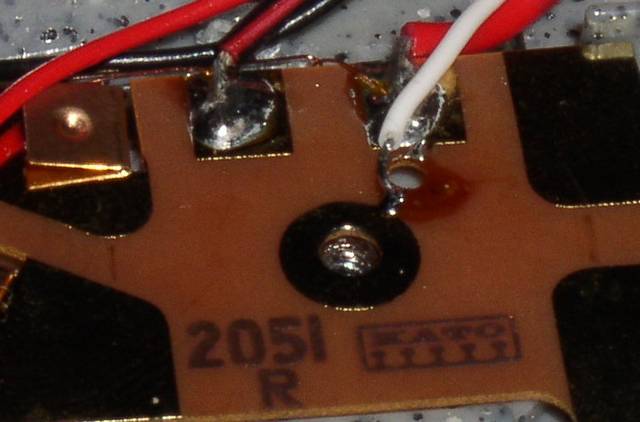
Here is a circuit I came up with to indicate the status of Kato turnouts:
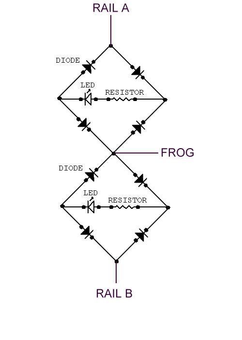
This circuit has some advantages and disadvantages. First, the main disadvantage: when operating in DC the LEDs only light when power is applied to the track. For example, when a train is approaching the turnout, the appropriate LED will be lit, but if the train is stopped, the LED will go out.
Now for the advantages: Will work for both DC and DCC. Works regardless of the method used to throw the turnout, even works if the turnout is thrown manually by the built in slide switch. Can be built completely into the turnout, handy for temporary layouts.
Some pictures of the circuit in a turnout:
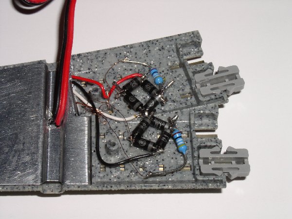
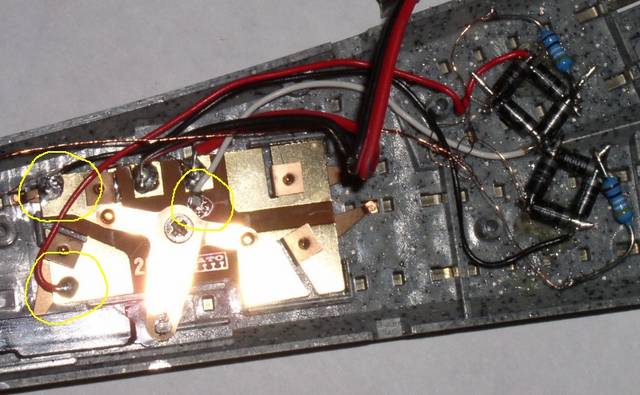
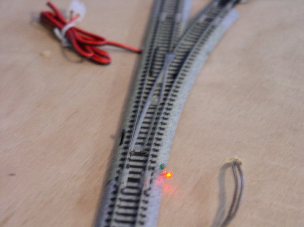
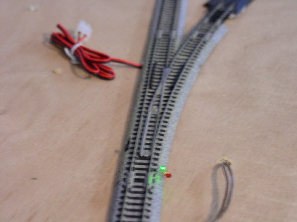
Operating(I plan to make a drawf signal out of the LEDs, but they are currently just hanging by their wires):
This circuit has some advantages and disadvantages. First, the main disadvantage: when operating in DC the LEDs only light when power is applied to the track. For example, when a train is approaching the turnout, the appropriate LED will be lit, but if the train is stopped, the LED will go out.
Now for the advantages: Will work for both DC and DCC. Works regardless of the method used to throw the turnout, even works if the turnout is thrown manually by the built in slide switch. Can be built completely into the turnout, handy for temporary layouts.
Some pictures of the circuit in a turnout:
Operating(I plan to make a drawf signal out of the LEDs, but they are currently just hanging by their wires):
OK, I am attempting to get my mind around the BASIC circuit diagrahm. Since I do not know all the electric circuit symbols I do have some problems. First I assume that "S1" is the SDPT toggel.
S1 is a single pole double throw toggle.
The bottom line is the common from the power sourse. Is Vs1 and Vs2 the 12 volt power sourses (only reversed to give reversed polarity to the S1)?
Yes, in my system I used a bridge rectifier type supply with the center tap of the transformer as the common. This gives dual voltages. The supply is laid out on the PC board. All parts, even the transformer, mount on the board.
Since I am small and won't have track signels (at least at the start) I believe that I don't need the DL1 and DL2?
DL1 and 2 are shown as incandescent lamps, but can also be bipolar or conventional LED's with the addition of a series resistor. They are indicators only, unnecessary for function.
C1 is a capacitor that keeps power away from the switchs unless the toggle is switched?
C1 does two things. It limits the time high current is applied to the solenoid coils to the charging time of the capacitor, and it also doubles initial voltage. This makes the action very positive without causing any damaging temperature rise in the coils.
The points move rapidly and firmly, and can be instantly reversed with this system (no waiting for recharge)!
So the main difference from my original setup is that two transformers are used one + to S1 and one - to S1. Then C1 only allows momentrary pulse to the turnout, either + or - depending on which way S1 is switched and then does not allow current all the time as is needed for the LEDs? I do not see "all the time" power to the LEDs since one line from the LEDs is beyond C1. Here's were I really need help.
This system takes either two stiff supplies or one dual polarity supply. My board has the transformer and supply on the board, so the board runs off either 120 VAC or 12/24 AC by bridging the secondary with a low voltage AC source.
The direction indicator works because it indicates "charge" direction across the capacitor. The charge direction varies of course with the supply polarity.
The charge/discharge path for C1 is dependent on the wiring to the turnout and the turnout, so if anything opens the indicators will not work.
Since LED path resistance is much higher than turnout path resistance, the toggle indicator LED's do not affect operation.
Affiliate Disclosure: We may receive a commision from some of the links and ads shown on this website (Learn More Here)